Temperature limiter mounting structure and heater

A technology of installation structure and temperature limiter, which is applied in heating methods, lighting and heating equipment, household heating, etc., can solve the problems of complex assembly process and high assembly cost of temperature limiter, and achieve simple structure, high assembly efficiency, and easy assembly. The effect of simple process

Pending Publication Date: 2020-05-15
GREE ELECTRIC APPLIANCES INC
View PDF0 Cites 0 Cited by
  • Summary
  • Abstract
  • Description
  • Claims
  • Application Information

AI Technical Summary

Problems solved by technology

[0004] Therefore, the technical problem to be solved by the present invention is to overcome the defe

Method used


Image

  • Temperature limiter mounting structure and heater
  • Temperature limiter mounting structure and heater
  • Temperature limiter mounting structure and heater

Examples


Embodiment 1

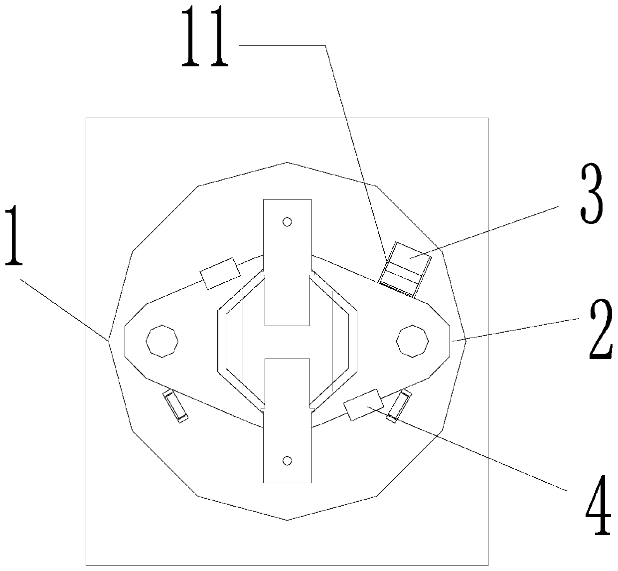
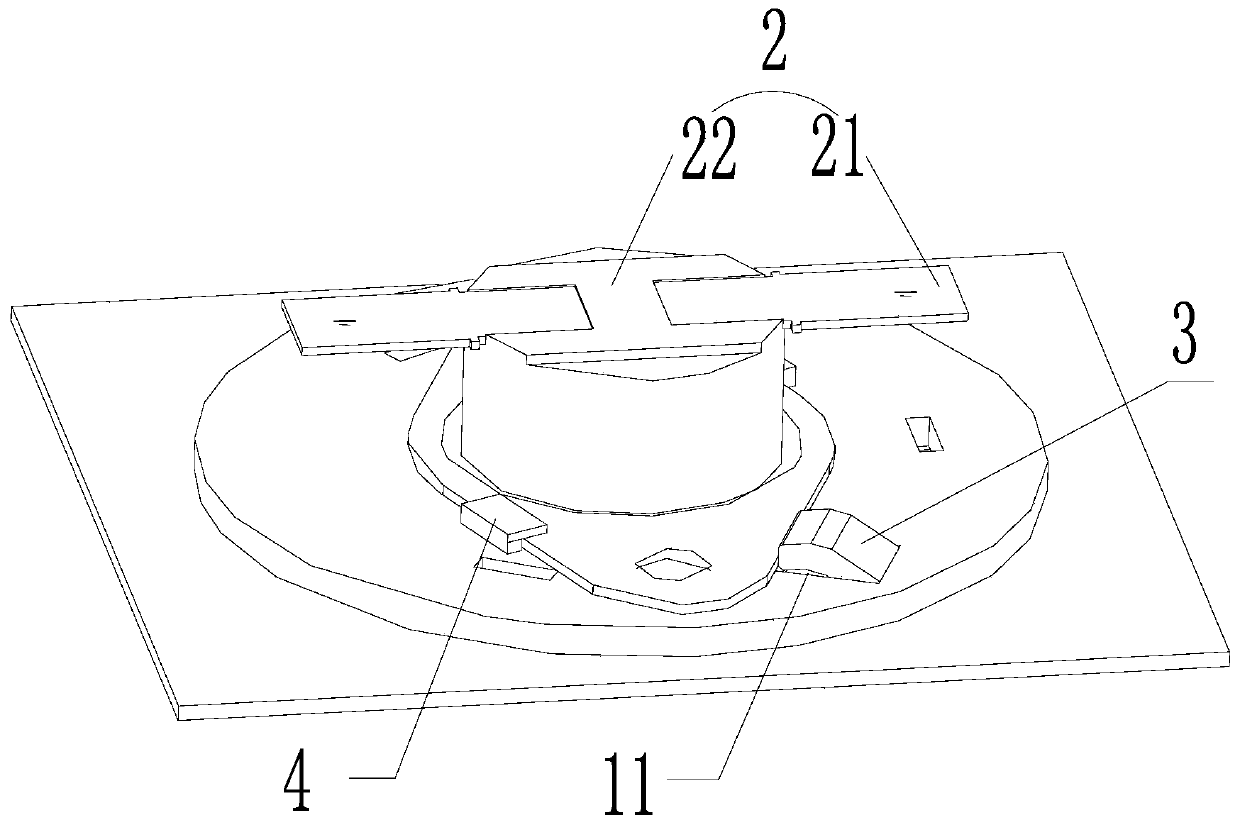
[0042] This embodiment provides a temperature limiter installation structure, such as figure 1 , figure 2 and image 3 As shown, it includes: a connection chuck 1; a temperature limiter 2, which is rotatably arranged on the connection chuck 1; at least one snap button 3, which is arranged behind the movement path of the temperature limiter 2 and connected to the On the connection chuck 1, the top end of the snap button 3 extends toward the temperature limiter 2, and the connection chuck 1 is provided with a notch 11 suitable for the insertion of the snap button 3; two limit positions A plate 4 is provided with an inlet suitable for the connection chuck 1 to enter, and the limiting plate 4 is arranged in front of the movement path of the temperature limiter 2 .

[0043] In this example, if figure 2 As shown, the limiter includes a main body 22 and a connecting plate 21 connected to the main body 22, the main body 22 is arranged at the center of the connecting plate 21, the...

Embodiment 2

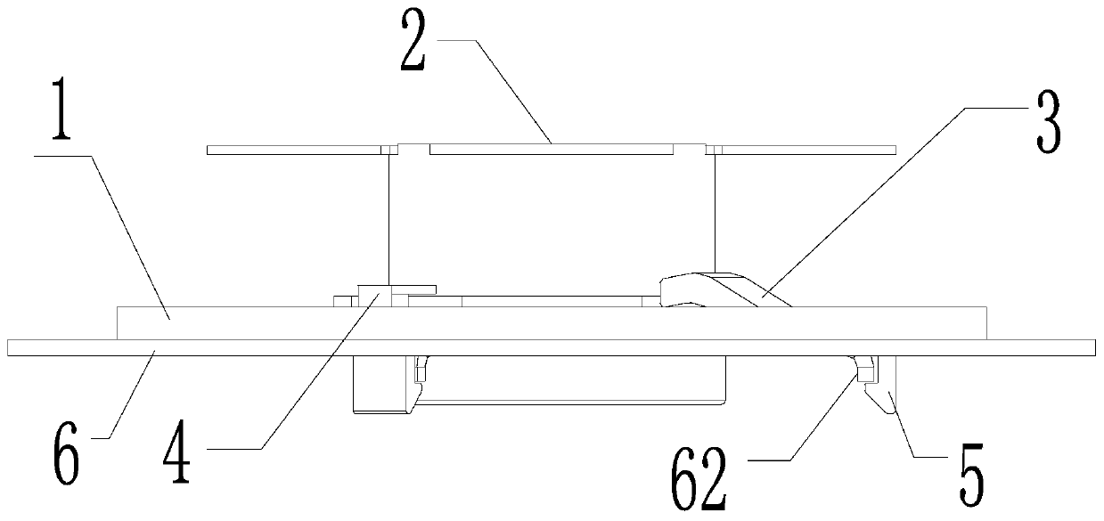
[0056] This embodiment provides a heater, including: a housing 6; the installation structure of the temperature limiter provided in Embodiment 1, the connection chuck 1 of the installation structure of the temperature limiter 2 is detachably arranged on the housing 6 .

[0057] Through the combination of the limiting plate 4 and the spring buckle 3, it is possible to avoid separately setting screws to fix the temperature limiter 2, saving materials and reducing manufacturing costs. At the same time, the assembly process of the temperature limiter 2 is simple and the assembly efficiency is high, which helps to reduce the labor cost in the production process of the heater. In addition, through the integrated assembly structure, the temperature limiter 2 can be directly installed on the heater, and the structure is simple.

[0058] In the heater provided in this embodiment, the casing 6 is provided with a through hole 61 , and the buckle 5 of the connection chuck 1 is connected ...


PUM


Abstract

The invention provides a temperature limiter mounting structure and a heater. The temperature limiter mounting structure comprises a connecting chuck, a temperature limiter, at least one elastic buckle and two limiting plates. The temperature limiter is rotationally arranged on the connecting chuck. The elastic buckle is arranged behind the motion path of the temperature limiter and is connected to the connecting chuck, the top end of the elastic buckles extend in the direction of the temperature limiter, and the connecting chuck is provided with gaps allowing the elastic buckles to be embedded. Inlets allowing the connecting chuck to enter are arranged on the two limiting plates, and the limiting plates are arranged in front of the motion path of the temperature limiter. In the temperature limiter mounting structure, through the combination of the limiting plates and the elastic buckles, the process of screws are independently arranged to fix the temperature limiter can be avoided, materials are saved, and manufacturing cost can be reduced. Meanwhile, the assembly process to the temperature limiter is simple, assembly efficiency is high, and the manual cost can be reduced easily.

Description

technical field [0001] The invention relates to the technical field of heaters, in particular to a temperature limiter installation structure and a heater comprising the same. Background technique [0002] Heaters are very common electrical appliances in people's daily life. Common heaters such as electric heaters and oil heaters have the advantages of environmental protection, heating blocks, and no noise. [0003] In heaters in the prior art, in order to avoid danger due to excessive temperature rise, a temperature limiter is usually added to the heater. When the temperature is too high, the temperature limiter will automatically cut off the power to ensure that the heater is always kept within the limited temperature. For the heater in the prior art, it is usually assembled by screws. This assembly method requires auxiliary equipment such as a separate screwdriver. The installation and removal process of the temperature limiter is relatively complicated, and adding screws...

Claims


Application Information

Patent Timeline
IPC IPC(8): F16B1/02F16B13/08F24D13/00F24D19/10
CPCF16B1/02F16B13/0825F24D13/00F24D19/1096F16B2200/81
Inventor 邵勤周小兵王超张毅廖泓斌
Owner GREE ELECTRIC APPLIANCES INC
Why Eureka
Try Eureka