Grating three-dimensional scanner moire fringe elimination method based on DLP projection

A moiré fringe and scanner technology, applied in the field of 3D measurement, can solve problems such as unfavorable high-precision measurement, influence of grating 3D measurement accuracy, large resolution difference, etc.

Active Publication Date: 2020-05-15
武汉玄景科技有限公司
View PDF6 Cites 0 Cited by
  • Summary
  • Abstract
  • Description
  • Claims
  • Application Information

AI Technical Summary

Problems solved by technology

The phase error caused by Moiré fringes has a relatively large impact on the three-dimensional measurement accuracy of the grating
[0004] In order to reduce the influence of the Moire effect on the three-dimensional measurement accuracy of the grating, one method is to ensure that there is a large frequency difference between the spatial sampling frequency of the DLP and the CCD image sensor. A large frequency difference means a relatively large difference in resolution, which is not conducive to high-precision measurement, so it is not practical; another method is to use the defocused projection method to suppress the high frequency components to reduce moiré, but this method also suppresses the high frequency components of the phase shift grating, reducing the measurement details and accuracy

Method used


Image

  • Grating three-dimensional scanner moire fringe elimination method based on DLP projection
  • Grating three-dimensional scanner moire fringe elimination method based on DLP projection
  • Grating three-dimensional scanner moire fringe elimination method based on DLP projection

Examples


Embodiment Construction

[0074] The technical solutions of the present invention will be described in detail below in conjunction with the accompanying drawings and examples, and the technical solutions in the embodiments of the present invention will be clearly and completely described. Obviously, the described embodiments are only part of the embodiments of the present invention, not all of them. Way. Based on the implementation manners in the present invention, all other implementation manners obtained by persons of ordinary skill in the art without making creative efforts belong to the scope of protection of the present invention.

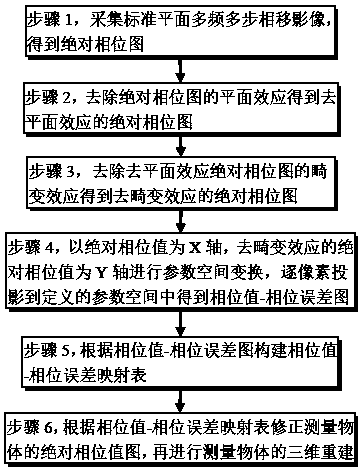
[0075] The present invention aims at the moiré fringe phenomenon existing in the raster three-dimensional scanning of DLP projection, and provides a moiré fringe elimination method without loss of accuracy and details, such as image 3 shown, including the following steps:

[0076] Step 1, collecting standard planar multi-frequency and multi-step phase shift images, u...


PUM


Abstract

The invention provides a grating three-dimensional scanner moire fringe elimination method based on DLP projection. The grating three-dimensional scanner moire fringe elimination method comprises thesteps: collecting a standard plane multi-frequency multi-step phase shift image to obtain a standard plane absolute phase diagram; removing the planar effect according to the absolute phase diagram toobtain an absolute phase diagram without the planar effect; removing the distortion effect according to the absolute phase diagram of the deplanarization effect to obtain an absolute phase diagram ofthe dedistortion effect; performing parameter space transformation on the absolute phase diagram and the absolute phase diagram of the dedistortion effect to obtain a phase value-phase error diagram;obtaining a phase value-phase error mapping table according to the phase value-phase error graph; and acquiring a multi-frequency multi-step phase shift image of the measured object, performing absolute phase diagram correction according to the phase value-phase error mapping table, and then performing three-dimensional reconstruction of the measured object. According to the method, the moire fringes existing in DLP projection grating three-dimensional scanning can be eliminated under the condition that the reconstruction precision and reconstruction details are guaranteed, and the measurement effect of the DLP projection-based grating three-dimensional scanner is improved.

Description

technical field [0001] The invention relates to the field of three-dimensional measurement, in particular to a method for eliminating Moiré fringes of a raster three-dimensional scanner based on DLP projection. Background technique [0002] Digital Light Processing (DLP) first digitally processes the image signal and then projects the light. DLP uses the digital micromirror chip (DigitalMicroMirror Device, DMD) developed by TI (Texas Instruments) as the main key processing element to realize the digital optical processing process. DMD is a digital optical switch, which is composed of many small square mirrors with a side length of 16 μm, and each small mirror represents a pixel of the projected image, such as figure 1 As shown, the main feature of DLP is that it can produce digital video images with high brightness, high resolution and high definition. Utilizing the programmability of DMD, the image projected by DLP can be generated by computer software according to the ne...

Claims


Application Information

Patent Timeline
Patent Type & Authority Applications(China)
IPC IPC(8): G01B11/25
CPCG01B11/25
Inventor 黄文超龚静刘改
Owner 武汉玄景科技有限公司
Why Eureka
Try Eureka