Measuring device and method for rock tensile strength

A technology for tensile strength and measuring devices, which is applied in the direction of measuring devices, strength characteristics, and the use of stable tension/compression to test the strength of materials, etc., which can solve the problems of difficult preparation of test pieces, large dispersion of test results, and impact on test accuracy, etc.

Active Publication Date: 2021-02-09
CENT SOUTH UNIV
View PDF6 Cites 0 Cited by
  • Summary
  • Abstract
  • Description
  • Claims
  • Application Information

AI Technical Summary

Problems solved by technology

[0004] (1) A more accurate tensile strength value can be obtained by using the direct tension method, but it is difficult to prepare the specimen by this method, the test technology is complicated, and the position of the tensile failure section of the specimen is difficult to control, and it is easy to connect the specimen to the fixture Broken, affecting the test accuracy;
[0005] (2) When the tensile strength value of the rock is measured by the splitting method, the compressive stress area near the contact position between the end of the sample and the loading block is unavoidable, resulting in the measured tensile strength value being too large;
[0006] (3) When the tensile strength value of the rock is measured by the point load test, the test results are highly discrete. In order to ensure the test accuracy, the test generally stipulates that each group of tests must reach a certain number, usually more than 15 test pieces, and then take Average, time consuming

Method used


Image

  • Measuring device and method for rock tensile strength
  • Measuring device and method for rock tensile strength
  • Measuring device and method for rock tensile strength

Examples


Embodiment Construction

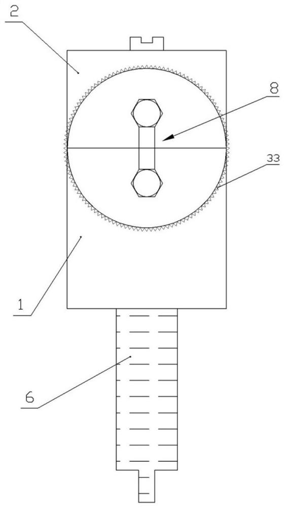
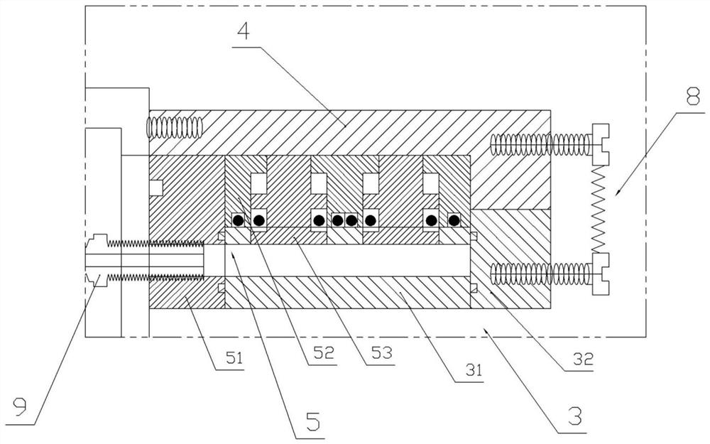
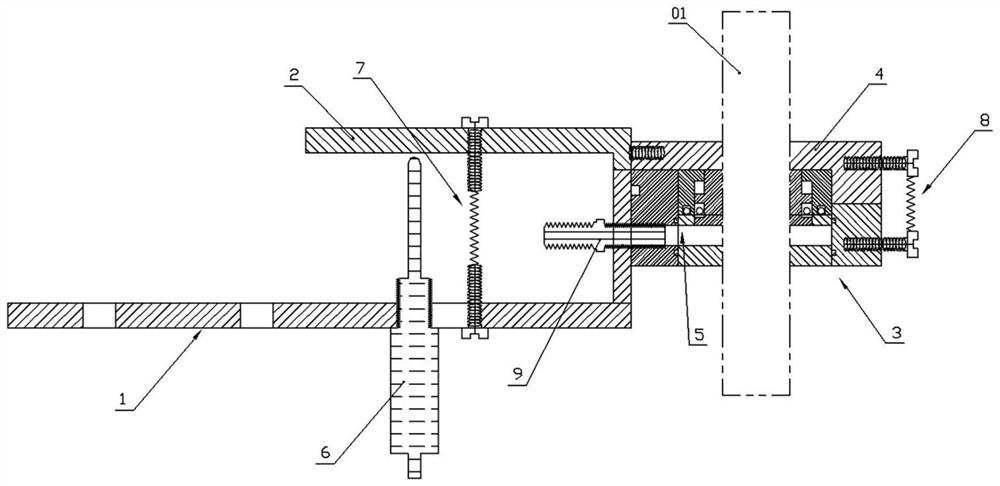
[0047] Such as figure 1 , figure 2 As shown, the rock tensile strength measuring device disclosed in this embodiment includes a lower seat 1, an upper seat 2, a lower pressure block 3, an upper pressure block 4, a force applying mechanism 5, a displacement sensor 6, a vertical Tension reset mechanism 7 and transverse tension reset mechanism 8.

[0048] Both the lower seat 1 and the upper seat 2 are L-shaped seat bodies. Both the horizontal section and the middle part of the vertical section of the lower seat 1 are provided with through holes, and the upper seat is buckled upside down on the lower seat and tensioned by the vertical tension reset mechanism 7, which includes a pair of tension bolts 71 With the tension spring 72, two tension bolts are arranged vertically relative to each other, the tension bolt on the top is threaded on the upper seat 2, the tension bolt on the bottom is threaded on the lower seat, and the tension spring is connected to the two tension bolts. ...


PUM


Abstract

The invention discloses a measuring device and method for rock tensile strength. The device includes a lower seat, an upper seat, a lower pressure-resistant block, an upper pressure-resistant block, a force applying mechanism and a displacement sensor; the force applying mechanism includes a cylinder liner and a piston The rod and the cylinder liner are set in the lower pressure-resistant block, the area between the bottom of the cylinder liner and the lower pressure-resistant block is a high-pressure chamber, and the top of the piston rod extends out of the cylinder liner to contact the upper pressure-resistant block; one side of the upper seat is in contact with the upper pressure-resistant block. The pressure blocks are connected, and a tension reset mechanism is set between the lower seat and the upper seat and / or between the lower pressure block and the upper pressure block; the lower seat and the lower pressure block are connected through a high-pressure joint, and the output port of the high-pressure joint is connected to the The high-pressure chamber is connected, and the input from the high-pressure joint drives the movement of the piston rod to realize the expansion of the lower pressure-resistant block and the upper pressure-resistant block to cause tensile failure of the rock sample to be tested. The rock sample to be tested cracks from the separation of the upper and lower pressure blocks, and the cracking position of the test is controllable, thus ensuring the repeatability of the test.

Description

technical field [0001] The invention belongs to the technical field of indoor testing of rock mechanical properties, in particular to a measuring device and a measuring method for rock tensile strength. Background technique [0002] The tensile strength of rock is an important mechanical property of rock, and it is also an important parameter in the stability analysis of rock structure. The tensile strength of rock is much smaller than its compressive strength. When the tensile stress on the rock is higher than the tensile strength of the rock, the rock will undergo tensile failure. Therefore, it is of great significance to accurately obtain the tensile strength of the rock for the study of rock failure. [0003] At present, the methods for measuring the tensile strength of rocks include direct tension method, split method and point load method. However, these testing methods have some shortcomings: [0004] (1) A more accurate tensile strength value can be obtained by usi...

Claims


Application Information

Patent Timeline
Patent Type & Authority Patents(China)
IPC IPC(8): G01N3/10G01N3/06
CPCG01N3/06G01N3/10G01N2203/0017G01N2203/0048G01N2203/0075G01N2203/0274G01N2203/0411G01N2203/0676G01N2203/0682
Inventor 王少锋孙立成景岳唐宇
Owner CENT SOUTH UNIV
Why Eureka
Try Eureka