
Pod attitude real-time measuring, resolving and monitoring device

A technology of real-time measurement and monitoring devices, applied in the directions of measuring devices, measuring angles, surveying and navigation, etc., can solve the problem of real-time monitoring of attitude information without considering the ground personnel, the complicated way of conversion and calculation process, and the lack of consideration of GPS antenna Placement point errors and other problems, to ensure real-time measurement, improve the efficiency of calculation, and save space

Active Publication Date: 2020-05-15
JILIN UNIV
View PDF11 Cites 8 Cited by
  • Summary
  • Abstract
  • Description
  • Claims
  • Application Information

AI Technical Summary

Problems solved by technology

In the above invention patents, the GPS antennas are all placed on a single plane supported by a fixed mechanical structure, and the problem of errors caused by the placement of the GPS antenna away from the plane is not considered; the acquisition of the test results involves the conversion calculation process of the coordinate system. Compared with the present invention The calculation method based on the ground base station is more complicated, and it does not consider the real-time monitoring of attitude information by ground personnel

Method used


Image

  • Pod attitude real-time measuring, resolving and monitoring device
  • Pod attitude real-time measuring, resolving and monitoring device
  • Pod attitude real-time measuring, resolving and monitoring device

Examples


Embodiment 1

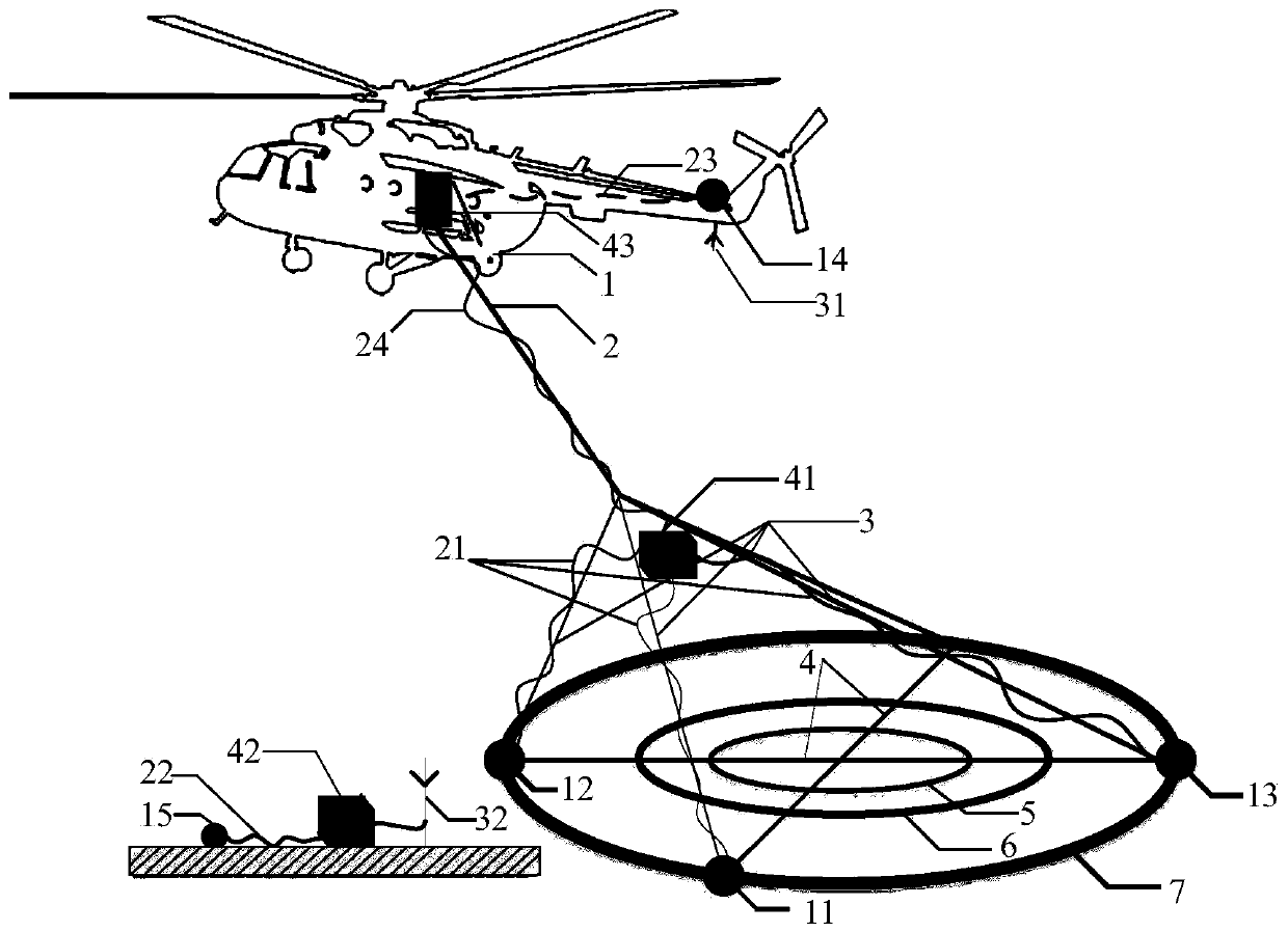
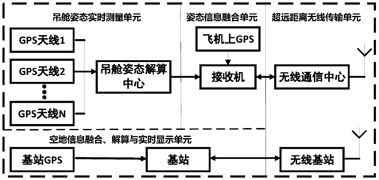
[0061] see figure 1 and image 3 As shown, the pod attitude real-time measurement, calculation and monitoring device, when the helicopter 1 and the pod (pod load-bearing rope 2, pod suspension rope 3, pod horizontal stay rope 4. In the pod-type time-domain aeronautical electromagnetic detection system composed of receiving coil 5, compensation coil 6 and transmitting coil 7, the pod horizontal stay rope 4, receiving coil 5, compensating coil 6 and transmitting coil 7 are all on the plane of the pod The main GPS antenna 11 placed on the pod, the secondary GPS antenna 12, the secondary GPS antenna 13 and the additional GPS antenna added according to requirements, the attitude measurement GPS antenna connection line 21, and the pod attitude calculation center 41 together constitute the pod attitude The real-time measurement unit obtains the attitude change of the pod relative to the main GPS antenna. The pod attitude calculation center transmits the pod attitude data to the rece...

Embodiment 2

[0114] The difference from Embodiment 1 is that one master GPS antenna and three slave GPS antennas are used. Before the pod attitude calculation center is used to calculate the pod attitude, it is first necessary to pass the GPS antenna on the plane without forming a plane to the plane. The determined pod plane:

[0115] see Figure 5 As shown, a main GPS antenna 11 named O is installed on the pod, and three slave GPS antennas are named A, B, and C respectively, and the four antennas are evenly distributed on the circular transmitting coil skeleton.

[0116] As shown in Figure 6, the four GPS antennas pass through the above Figure 4 After the fixed bracket is fixedly connected with the transmitting coil skeleton, with the main GPS antenna as the apex, there are OAC ( Figure 6a ), OAB ( Figure 6b ), OBC ( Figure 6c ) three planes, select the plane that is not on the plane and the shortest distance from the antenna to the plane as the plane of the pod. For example, the...

Embodiment 3

[0118] The difference from Embodiment 1 and Embodiment 2 is that the plane with the shortest sum of distances from the two antennas that are not on the plane to the plane needs to be used as the plane of the pod

[0119] see Figure 7 , a main GPS antenna (11) is installed on the pod to name O, and four auxiliary GPS antennas are named A, B, C, D respectively, and five antennas are evenly distributed on the circular transmitting coil skeleton.

[0120] see Figure 8 , the four GPS antennas pass the above Figure 4 After the fixed bracket is fixedly connected with the transmitting coil frame, with the main GPS antenna as the vertex, there are six planes OAB(a), OAC(b), OAD(c), OBC(d), OBD(e), and OCD(f) , select the plane that is shortest from the sum of the distances from the other two antennas to the plane that is not on the plane as the plane of the pod. For example,


PUM


Abstract

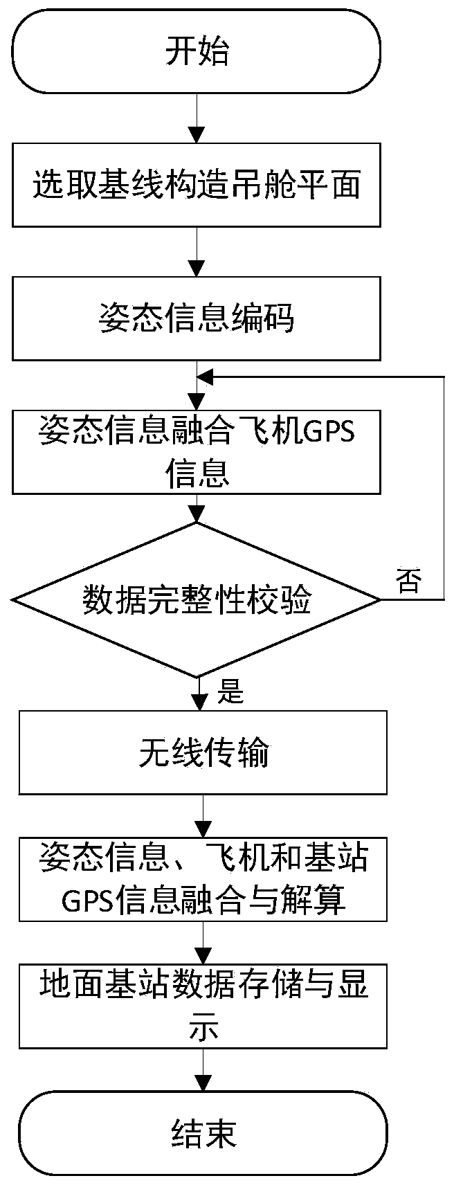
The invention discloses a pod attitude real-time measuring, resolving and monitoring device. Position change information of multiple points on the pod is obtained through a plurality of GPS antennas placed on the pod. A pod attitude calculation center calculates attitude information of a pod plane in real time. A resolving result is transmitted to the receiver. The receiver fuses the GPS information of the aircraft and the pod attitude information and then transmits the information to the ground base station in real time through the wireless transmission unit. The ground base station integrates GPS information of the ground base station and information transmitted by the air receiver to calculate attitude and position information of the nacelle relative to the base station, attitude and position information of the nacelle relative to the aircraft and position information of the aircraft relative to the base station. After the test is finished, the ground base station performs data fusion on the electromagnetic data obtained by the system test and the stored and interpolated attitude information. According to the invention, real-time calculation and monitoring of the attitude of thenacelle and the motion state between the nacelle and the flight platform by ground personnel in a complex electromagnetic environment generated during normal flight testing of the system are realized.

Description

technical field [0001] The invention belongs to the field of time-domain aeronautical electromagnetic detection, in particular to a device for real-time measurement, calculation and monitoring of pod attitude. Background technique [0002] The time-domain aeronautical electromagnetic detection system will generate a strong electromagnetic field that changes with time during normal operation. In order to avoid affecting the normal operation of the system, the pod attitude measurement system needs to use non-metallic materials as much as possible and keep away from the receiving coil. The test process is as free as possible. Influenced by a strong and changing electromagnetic field; in addition, during the flight, due to factors such as the flight speed of the aircraft, the uneven force of the pod suspension rope, the gravity of the large-size pod, and wind resistance, any point on the transmitting coil skeleton and its nearby points It may be a certain distance away from the ...

Claims


Application Information

Patent Timeline
IPC IPC(8): G01S19/53G01C1/00G01C5/00G01V3/16G01V3/165
CPCG01S19/53G01C1/00G01C5/005G01V3/16G01V3/165
Inventor 王言章许权王世隆王麒白一帆
Owner JILIN UNIV
Learn More