Automatic equipment positioning control mechanism

A technology of automation equipment and positioning control, applied in the direction of electric speed/acceleration control, etc., can solve the problems of poor positioning effect, rigid and complicated structure, etc., and achieve the effect of convenient positioning control and convenient position correction.

Inactive Publication Date: 2020-05-15
南京亚克电子有限公司
View PDF0 Cites 1 Cited by
  • Summary
  • Abstract
  • Description
  • Claims
  • Application Information

AI Technical Summary

Problems solved by technology

[0004] At present, the positioning control mechanism of automation equipment has a rigid and complex structure, and the positioning effect is poor. Therefore, the inventor proposed a positioning control mechanism for automation equipment

Method used


Image

  • Automatic equipment positioning control mechanism
  • Automatic equipment positioning control mechanism
  • Automatic equipment positioning control mechanism

Examples


Embodiment 1

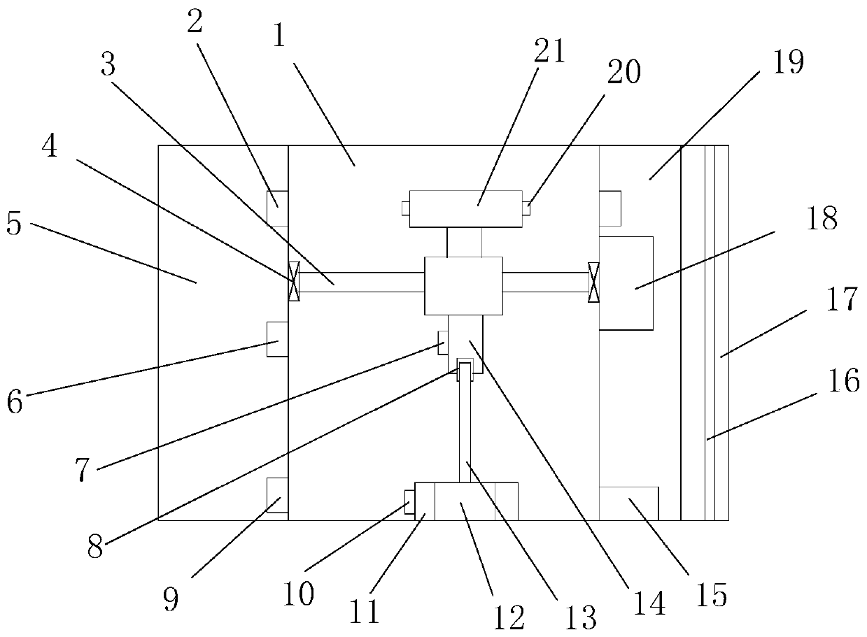
[0027] Example 1, please refer to Figure 1~3 , a positioning control mechanism for automation equipment, including a positioning bin 1, a moving mechanism is arranged in the outer bin, a workbench 21 is connected to the moving mechanism, and a second fixed seat 14 is arranged at the bottom of the workbench 21. The second Below the fixed seat 14, a card seat 8 is arranged, and the bottom of the positioning warehouse 1 is provided with a first fixed seat 11 corresponding to the lower part of the card seat 8. The first fixed seat 11 is provided with a diaphragm pressure sensor 12, and the diaphragm pressure sensor is provided with a There is a metal diaphragm 13, and the top of the metal diaphragm 13 is fixedly connected with the card seat 8. The left and right sides of the fixed outer bin are respectively provided with a support bin 5 and a driving bin 19, and the driving bin 19 is provided with a servo for driving the moving mechanism. motor 18.

[0028] When working, the dis...

Embodiment 2

[0032] Example 2, please refer to Figure 1~3 , a positioning control mechanism for automation equipment, including a positioning bin 1, a moving mechanism is arranged in the outer bin, a workbench 21 is connected to the moving mechanism, and a second fixed seat 14 is arranged at the bottom of the workbench 21. The second Below the fixed seat 14, a card seat 8 is arranged, and the bottom of the positioning warehouse 1 is provided with a first fixed seat 11 corresponding to the lower part of the card seat 8. The first fixed seat 11 is provided with a diaphragm pressure sensor 12, and the diaphragm pressure sensor is provided with a There is a metal diaphragm 13, and the top of the metal diaphragm 13 is fixedly connected with the card seat 8. The left and right sides of the fixed outer bin are respectively provided with a support bin 5 and a driving bin 19, and the driving bin 19 is provided with a servo for driving the moving mechanism. motor 18.

[0033] When working, the dis...

Embodiment 3

[0038] Embodiment three, please refer to Figure 1~3 , a positioning control mechanism for automation equipment, including a positioning bin 1, a moving mechanism is arranged in the outer bin, a workbench 21 is connected to the moving mechanism, and a second fixed seat 14 is arranged at the bottom of the workbench 21. The second Below the fixed seat 14, a card seat 8 is arranged, and the bottom of the positioning warehouse 1 is provided with a first fixed seat 11 corresponding to the lower part of the card seat 8. The first fixed seat 11 is provided with a diaphragm pressure sensor 12, and the diaphragm pressure sensor is provided with a There is a metal diaphragm 13, and the top of the metal diaphragm 13 is fixedly connected with the card seat 8. The left and right sides of the fixed outer bin are respectively provided with a support bin 5 and a driving bin 19, and the driving bin 19 is provided with a servo for driving the moving mechanism. motor 18.

[0039] When working, ...


PUM


Abstract

The invention discloses an automatic equipment positioning control mechanism including a positioning bin; a moving mechanism is arranged in the positioning bin; the moving mechanism is connected witha workbench. A second fixed seat is arranged at the bottom of the workbench. A clamping seat is arranged below the second fixed seat; a first fixed seat is arranged at the bottom of the positioning bin corresponding to the lower part of the clamping seat; a diaphragm type pressure sensor is arranged on the first fixed seat; a metal diaphragm is arranged on the diaphragm pressure sensor; the top ofthe metal diaphragm is fixedly connected with the clamping seat, the left side and the right side of the fixed outer bin are provided with a supporting bin and a driving bin correspondingly, the diaphragm is creatively driven to deform in the moving positioning process, the pressure sensor is used for converting the diaphragm into an electric signal, the displacement of the workbench is obtainedthrough calculation, and positioning control is achieved. A laser emitter is further arranged, and a laser receiver is correspondingly arranged on the left side in the positioning bin. Displacement ismeasured through laser, open-loop positioning control is achieved, and measurement and positioning are achieved in cooperation with a diaphragm type pressure sensor.

Description

technical field [0001] The invention belongs to the technical field of automatic positioning, and specifically relates to a positioning control mechanism for automatic equipment. Background technique [0002] Positioning control means that when the controller issues control instructions according to the control requirements, the position of the controlled object will complete the specified displacement in the specified direction at the specified speed, that is, it will stably stop at the predetermined target point within a certain period of time. The positioning control system is a system that realizes positioning control. It can be mainly divided into open-loop position servo system, semi-closed-loop position control system, fully-closed-loop position control system, hybrid closed-loop position servo system. Whether it is in civil industry or in national economic construction, it has extremely broad application prospects; [0003] In the past, many units in China were eng...

Claims


Application Information

Patent Timeline
Patent Type & Authority Applications(China)
IPC IPC(8): G05D13/62
CPCG05D13/62
Inventor 郑之进
Owner 南京亚克电子有限公司
Why Eureka
Try Eureka