Storage battery safety box for new energy electric vehicle

A technology for electric vehicles and storage batteries, applied to batteries, secondary batteries, battery pack components, etc., can solve problems such as poor anti-vibration effect, low safety factor, tilted or damaged batteries, and achieve faster air flow rate and structural design Reasonable, position-keeping effect

Inactive Publication Date: 2020-05-15
陕西优民惠科技有限公司
View PDF0 Cites 4 Cited by
  • Summary
  • Abstract
  • Description
  • Claims
  • Application Information

AI Technical Summary

Problems solved by technology

[0002] With the support of the state and technological innovation, the field of new energy vehicles has been greatly developed, the market acceptance and recognition of new energy electric vehicles have been greatly improved, and new energy electric vehicles have continued to break through in cruising range. At present, the cruising range of new energy electric vehicles has reached 400 kilometers, which basically guarantees the travel needs of most people. Long-distance driving requires the support of battery technology, and batteries are the only energy source installed on new energy electric vehicles. It will have higher safety factor requirements than the batteries used in our daily life. Long-distance driving will cause high temperature on the surface of the battery, and collisions during driving will cause the battery to tilt or be damaged, resulting in electrolyte leakage. These may cause great safety hazards. Therefore, the battery needs to be protected, but the existing equipment has slow heat dissipation, poor anti-vibration effect, and cannot detect battery leakage, so the safety factor is low

Method used


Image

  • Storage battery safety box for new energy electric vehicle
  • Storage battery safety box for new energy electric vehicle
  • Storage battery safety box for new energy electric vehicle

Examples


Embodiment Construction

[0019] The following will clearly and completely describe the technical solutions in the embodiments of the present invention with reference to the accompanying drawings in the embodiments of the present invention. Obviously, the described embodiments are only some, not all, embodiments of the present invention. Based on the embodiments of the present invention, all other embodiments obtained by persons of ordinary skill in the art without creative efforts fall within the protection scope of the present invention.

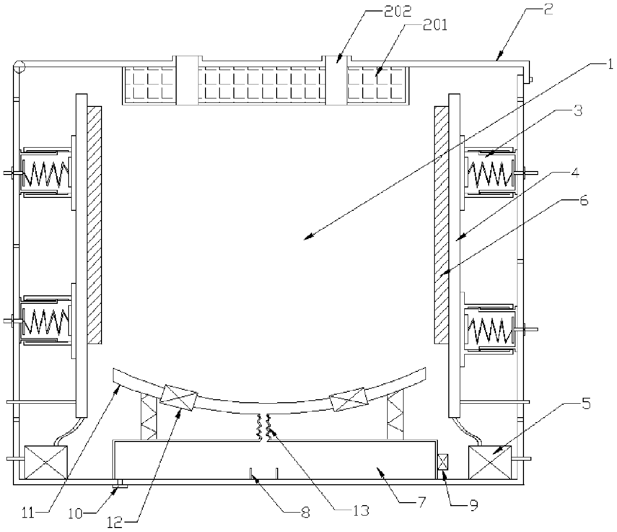
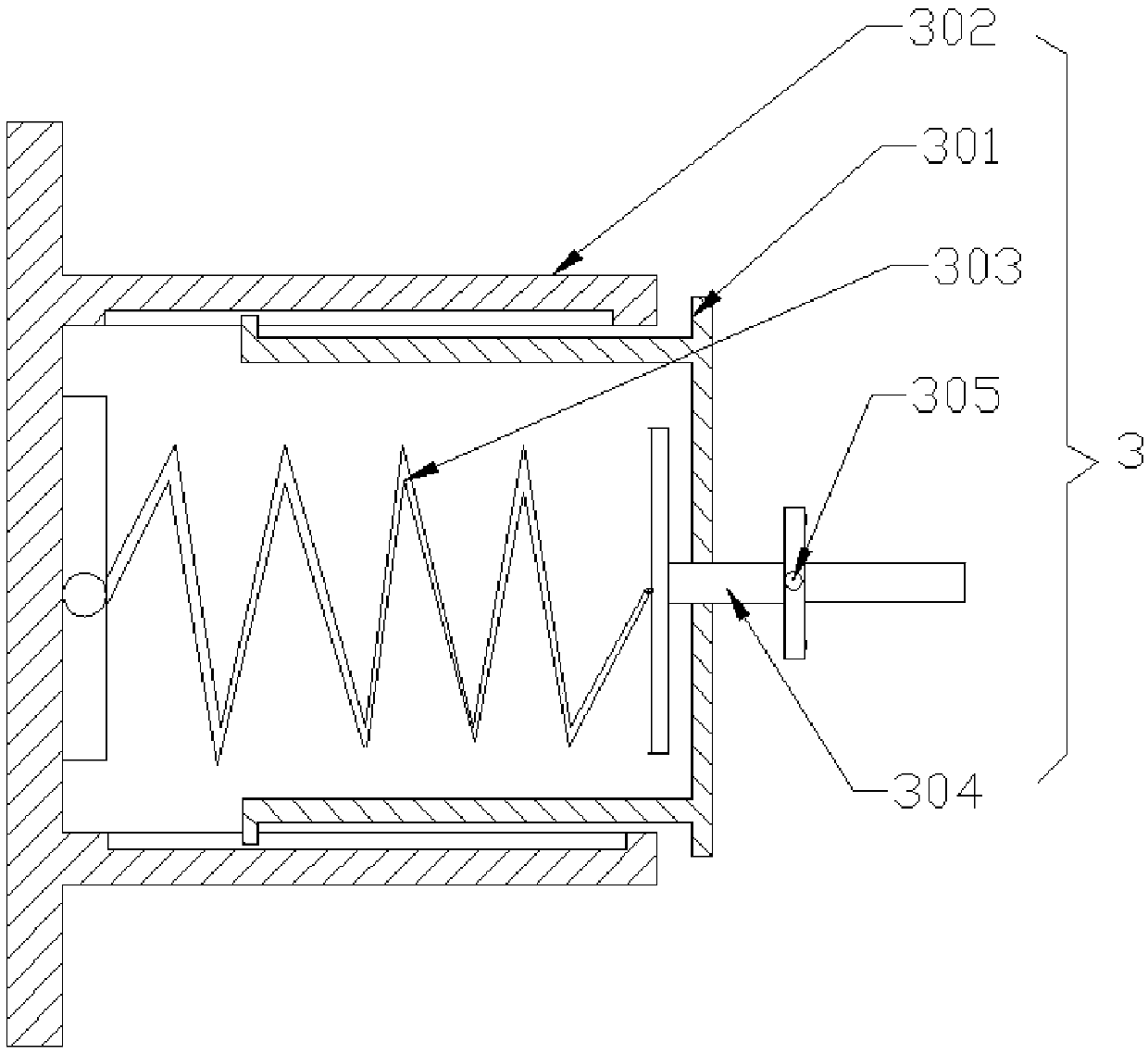
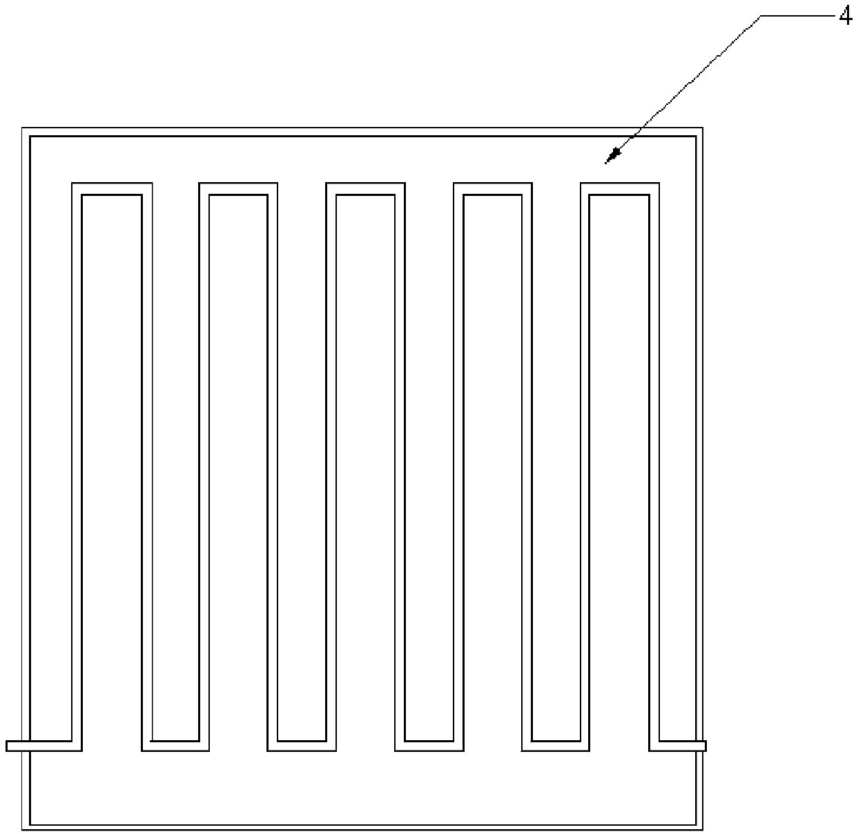
[0020] see Figure 1-4 As shown, this embodiment is a battery safety box for new energy electric vehicles, including a box body 1, a cover 2 is hinged on the left side of the top of the box body 1 through a hinge, and a buffer layer 201 is provided at the bottom of the cover body 2 , the left and right sides of the bottom of the buffer layer 201 are symmetrically fitted with a collection pipe 202, and the top of the collection pipe 202 runs through the cover body 2...


PUM


Abstract

The invention discloses a storage battery safety box for a new energy electric vehicle. The storage battery safety box comprises a box body, a cover body is hinged to the left side at the top of the box body through a hinge, and spring limiters are symmetrically arranged on the left side wall and the right side wall of an inner cavity of the box body. One sides, close to the center of the inner cavity of the box body, of the spring limiters are connected with the water cooling plates, and the heat conduction silica gel pads are arranged on the surfaces at the sides, close to the center of theinner cavity of the box body, of the water cooling plates, and a liquid storage tank is arranged in the center of the bottom of the inner cavity of the box body. An alarm is arranged on the right outer side wall of the liquid storage tank, a spring tray is arranged at the top of the liquid storage tank, and cooling fans are symmetrically embedded in the left and right sides of the spring tray. Thestorage battery safety box is reasonable in structural design, on one hand, the surface heat of a storage battery is absorbed through the heat exchange effect of the water cooling plates, and the airflow rate at the bottom of the storage battery is increased through the cooling fans, so that the purpose of rapid cooling is achieved. The alarm gives an early warning for the storage battery leakage to remind a vehicle owner to maintain in time.

Description

technical field [0001] The invention relates to the field of new energy sources for automobiles, in particular to a storage battery safety box for new energy electric vehicles. Background technique [0002] With the support of the state and technological innovation, the field of new energy vehicles has been greatly developed, the market acceptance and recognition of new energy electric vehicles have been greatly improved, and new energy electric vehicles have continued to break through in cruising range. At present, the cruising range of new energy electric vehicles has reached 400 kilometers, which basically guarantees the travel needs of most people. Long-distance driving requires the support of battery technology, and batteries are the only energy source installed on new energy electric vehicles. It will have higher safety factor requirements than the batteries used in our daily life. Long-distance driving will cause high temperature on the surface of the battery, and col...

Claims


Application Information

Patent Timeline
Patent Type & Authority Applications(China)
IPC IPC(8): H01M2/10H01M10/42H01M10/48H01M10/613H01M10/625H01M10/6551H01M10/6563H01M10/6568
CPCH01M10/4228H01M10/488H01M2220/20H01M10/613H01M10/625H01M10/6551H01M10/6563H01M10/6568H01M50/20Y02E60/10
Inventor 赵宏丽李西静
Owner 陕西优民惠科技有限公司
Why Eureka
Try Eureka