
Micromechanical presssure sensor device and corresponding production method

A pressure sensor and micro-mechanical technology, which is used in the measurement of fluid pressure, the pressure difference measurement between multiple valves, and the measurement of fluid pressure through electromagnetic components. It can solve the problems of reduced mechanical stability and pressure sensor tolerance. Achieve the effect of improved precision and high mechanical stability

Active Publication Date: 2020-05-15
ROBERT BOSCH GMBH
View PDF8 Cites 2 Cited by
  • Summary
  • Abstract
  • Description
  • Claims
  • Application Information

AI Technical Summary

Problems solved by technology

[0008] Either mechanical stresses in the pressure sensor device are coupled into the pressure measurement signal, or the decoupling of the mechanical stresses leads to a reduction in mechanical robustness, whereby known pressure sensors are in a certain way subject to errors

Method used


Image

  • Micromechanical presssure sensor device and corresponding production method
  • Micromechanical presssure sensor device and corresponding production method
  • Micromechanical presssure sensor device and corresponding production method

Examples


Embodiment Construction

[0028] In the figures, identical reference numbers indicate identical or functionally identical elements.

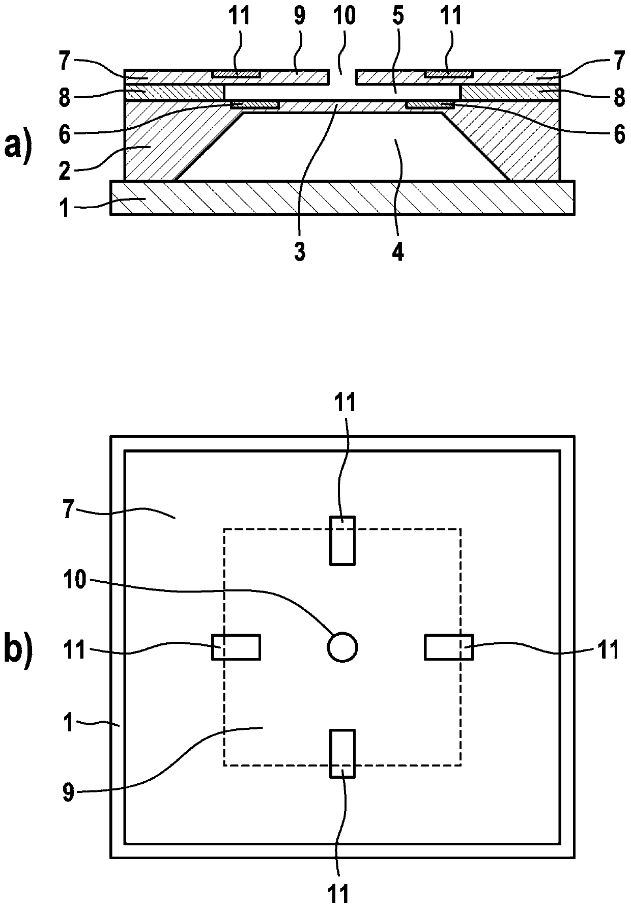
[0029] figure 1 a), b) are schematic representations of a micromechanical pressure sensor device according to a first embodiment of the invention, more precisely, figure 1 a) is a cross section and figure 1 b) is a top view.

[0030] exist figure 1 In a), b), the reference numeral 2 designates a first micromechanical functional layer, for example a silicon layer, in which the first membrane 3 and the cavity adjoining the first membrane are formed 4. A sealing layer 1 , for example likewise a silicon layer, is arranged on the side of the first micromechanical functional layer 2 opposite the membrane 3 , by means of which sealing layer the first cavity 4 is closed. In the present case, the first membrane 3 is likewise closed, so that a constant pressure is contained in the first chamber 4 .

[0031] A first bending sensing device 6 with a piezoresistive element i...


PUM


Abstract

The invention relates to a micromechanical pressure sensor device, and to a corresponding production method. The micromechanical pressure sensor device has a first membrane (3) and an adjoining firstcavern (4); a deformation detecting unit (6) arranged in and / or on the first membrane (3) for detecting a deformation of the first membrane (3) due to an external pressure change applied thereto, anddue to an internal mechanical deformation of the pressure sensor device; a second membrane (9) and an adjoining second cavern (5); and a second deformation detecting unit (11) arranged in and / or on the second membrane (9) for detecting a deformation of the second membrane (9) due to the internal mechanical deformation of the pressure sensor device, wherein the second membrane (9) is designed suchthat it cannot be deformed as a result of the external pressure change.

Description

technical field [0001] The invention relates to a micromechanical pressure sensor device and a corresponding production method. Background technique [0002] Although applicable to any desired micromechanical pressure sensor device, the invention and the problem underlying the invention are explained with reference to a silicon-based micromechanical pressure sensor device, as is known from WO 2013 / 152901 A1. [0003] Figure 5 a)-c) are schematic representations of an exemplary micromechanical pressure sensor device for illustrating the problem underlying the present invention, more precisely, Figure 5 a), 5b) are cross sections and Figure 5 c) is a top view. [0004] exist Figure 5 In a) and 5b), the reference symbol F designates a micromechanical functional layer, for example a silicon layer. In the micromechanical functional layer F, a membrane M is formed with a cavity A arranged beneath it. The chamber A is closed by a sealing layer V on the rear side. [0005] Re...

Claims


Application Information

Patent Timeline
Patent Type & Authority Applications(China)
IPC IPC(8): G01L9/00G01L9/02G01L9/04G01L13/02G01L15/00
CPCG01L9/0041G01L9/0073G01L9/008G01L9/02G01L9/04G01L13/026G01L15/00G01L9/06B81B3/0072B81B2201/0264B81B2203/0127
Inventor R·毛尔F·霍伊克
Owner ROBERT BOSCH GMBH
Learn More