
Camera localization based automatic fire monitor target longitude and latitude calculating method

A calculation method and camera technology, applied in the field of image processing and fire-fighting automatic cannon, can solve the problems of many parameters, complex calculation, unable to solve the coordinate system transformation, etc., to achieve the effect of calculation and error-free calculation

Active Publication Date: 2020-05-19
SHENYANG TIANMU TECH
View PDF7 Cites 3 Cited by
  • Summary
  • Abstract
  • Description
  • Claims
  • Application Information

AI Technical Summary

Problems solved by technology

[0009] Aiming at the problems of many parameters, complex calculations, and inability to solve coordinate system transformation in the existing technology, the present invention provides a fast calculation method of ground coordinates and latitude and longitude independent of parameters such as height, and an improved calculation method under the premise of coordinate system transformation
[0011] 1. The method for calculating the longitude and latitude of the automatic fire monitor target based on camera positioning proposed by the present invention can solve the problem of many parameters and complex calculations in the existing technology, and can achieve real real-time calculation;

Method used

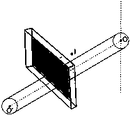

Image

  • Camera localization based automatic fire monitor target longitude and latitude calculating method
  • Camera localization based automatic fire monitor target longitude and latitude calculating method
  • Camera localization based automatic fire monitor target longitude and latitude calculating method

Examples


Embodiment Construction

[0021] The present invention will be further described in detail below in conjunction with the accompanying drawings and specific embodiments.

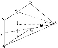
[0022] figure 1 A schematic diagram of camera-related parameters in this method is shown. In the picture I 3 is the center of the optical axis, that is, the optical center. w and h are the horizontal and vertical resolutions of the camera respectively, and the unit is pixel. β and γ are the horizontal and vertical viewing angles of the camera. a 1 to a 4 The points are the four corner points of the image. Here set a 1 point is the origin of image coordinates, then a 1 to a 4 The point coordinates are: , , , .

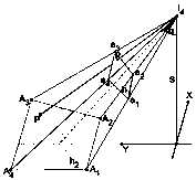
[0023] figure 2 Schematic diagram of camera perspective projection. In the figure h 1 is the imaging plane, which can revolve around the optical center I 4 Free rotation, the height of the optical center is S, and the angle between the optical axis and the z direction is α. plane h 1 Perspective project...


PUM


Abstract

The invention relates to a camera localization based automatic fire monitor target longitude and latitude calculating method. The camera localization based automatic fire monitor target longitude andlatitude calculating method comprises the following steps: utilizing perspective to transform a corresponding camera imaging plane and a ground plane, and converting coordinates of the ground plane into longitude and latitude coordinates through gnomonic projection. The method is irrelevant to parameters such as height and a distance, and really realizes real-time calculation. Furthermore, the invention discloses an error source and a solution while the camera coordinates are inconsistent with a rotation axis coordinate system, and provides theoretical foundation and a calculating method for guiding multiple fire monitors to simultaneously locate targets by a single camera. Moreover, the calculating method is suitable for positioning ground coordinates in the firefighting field, and is also suitable for the scenes of locating an unmanned aerial vehicle in the sky, and the like.

Description

technical field [0001] The invention relates to the field of image processing and automatic fire monitors, in particular to a camera-based automatic fire monitor positioning coordinate calculation method and an improved method when the camera and fire monitor coordinate systems are inconsistent. Background technique [0002] At present, all automatic fire monitors that use image positioning are bound to the camera and the nozzle of the fire monitor, so that the optical axis of the camera is as parallel as possible to the central axis of the nozzle of the fire monitor. In this way, when the camera detects the fire point, it notifies the fire monitor transmission system to rotate, and stops when the fire point is located at the imaging center of the camera. Because the optical axis of the camera is parallel to the central axis of the nozzle of the fire monitor, without considering the error, the nozzle of the fire monitor is also aligned with the fire point by default at this ...

Claims


Application Information

Patent Timeline
Patent Type & Authority Applications(China)
IPC IPC(8): A62C31/00A62C37/00
CPCA62C31/00A62C37/00
Inventor 邱怀骏
Owner SHENYANG TIANMU TECH
Learn More