Medical pipeline cleaning and sterilizing machine and medical pipeline cleaning and sterilizing method

A pipeline cleaning and disinfection machine technology, which is applied in the direction of cleaning methods and utensils, disinfection, chemical instruments and methods, etc., can solve the problems of high physical energy consumption of operators, manual operations, sterilization operations, etc., and achieve enhanced cleaning effects and improved practical performance , the effect of low energy consumption

Inactive Publication Date: 2020-05-19
ZHONGSHAN FENGSHEN ELECTRICAL APPLIANCE CO LTD
0 Cites 4 Cited by

AI-Extracted Technical Summary

Problems solved by technology

[0003] The purpose of the present invention is to provide a medical pipeline cleaning and disinfecting machine to solve the above-mentioned background technology. In the process of cleaning pipelines in medical equipment, the operator usually holds a rod-shaped brush to clean the inner wall of the pipeline. Dust, although it can have a certain cleaning effect...

Abstract

The invention provides a medical pipeline cleaning and sterilizing machine and a medical pipeline cleaning and sterilizing method. The medical pipeline cleaning and sterilizing machine comprises a transparent barrel, wherein an ash removal and sterilization mechanism is arranged on the left side of the transparent barrel. Through the cooperation of the transparent barrel and the ash removal and sterilization mechanism, when a pipeline in medical equipment needs to be cleaned, a control switch is in a closed state to electrify a motor, so that the transparent barrel and a hair brush can rotate;a cylinder and the transparent barrel are inserted into the medical pipeline needing to be cleaned while a handle is grasped, and move forward at a constant speed; the hair brush can rotate with thetransparent barrel to clean the inner wall of the medical pipeline; meanwhile an ultraviolet light sterilization lamp is electrified, and can sterilize the inner wall of the medical pipeline; in the process, an operator does not need to manually rotate the hair brush, the required physical energy consumption is relatively low, and meanwhile the sterilization operation can be performed; and the practical performance is significantly improved.

Application Domain

Technology Topic

Image

  • Medical pipeline cleaning and sterilizing machine and medical pipeline cleaning and sterilizing method
  • Medical pipeline cleaning and sterilizing machine and medical pipeline cleaning and sterilizing method
  • Medical pipeline cleaning and sterilizing machine and medical pipeline cleaning and sterilizing method

Examples

  • Experimental program(1)

Example Embodiment

[0031] The technical solutions in the embodiments of the present invention will be clearly and completely described below in conjunction with the accompanying drawings in the embodiments of the present invention. Obviously, the described embodiments are only a part of the embodiments of the present invention, rather than all the embodiments. Based on the embodiments of the present invention, all other embodiments obtained by those of ordinary skill in the art without creative work shall fall within the protection scope of the present invention.
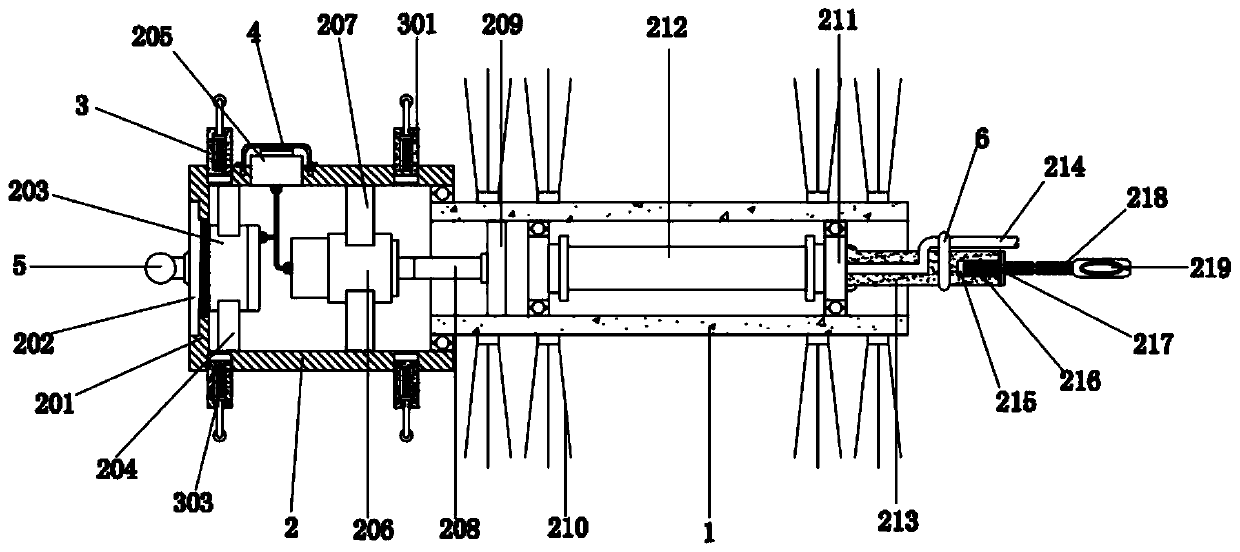
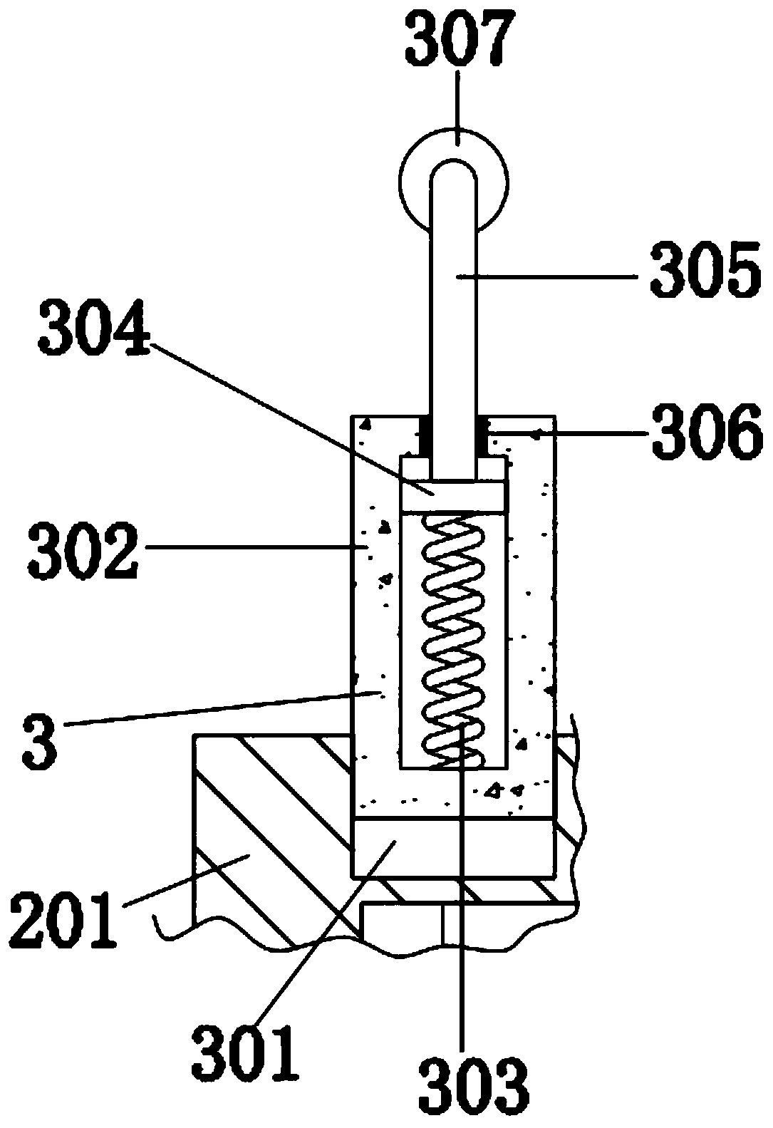
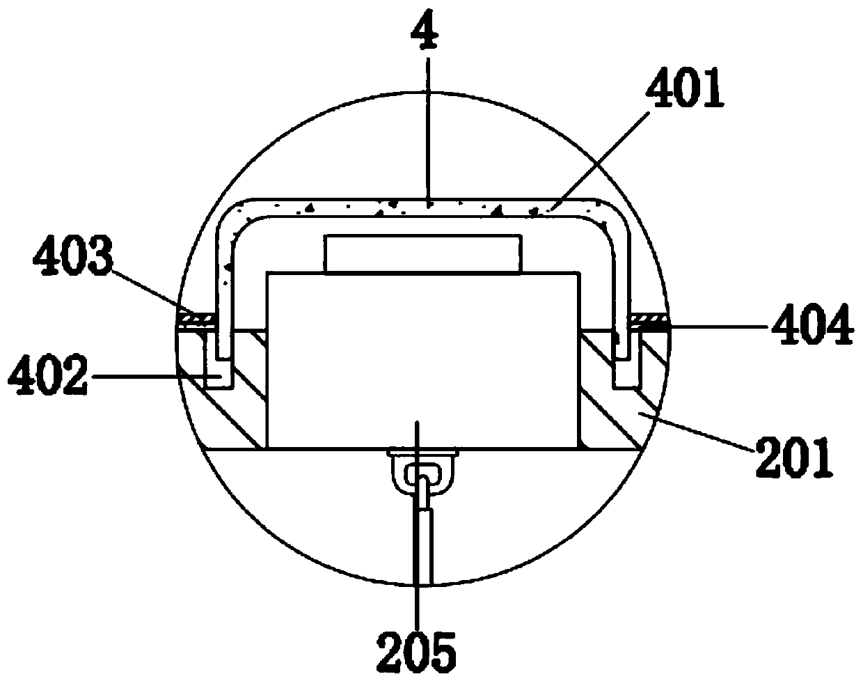
[0032] See Figure 1-6 , A medical pipeline cleaning and disinfection machine, including a transparent tube 1, the left side of the transparent tube 1 is provided with an ash cleaning and sterilizing mechanism 2, which includes a cylinder 201, a trapezoidal column 202, a battery 203, and a card board 204 , Control switch 205, motor 206, card holder 207, rotating rod 208, circular plate 209, brush 210, disc 211, ultraviolet sterilization lamp 212, cross bar 213, power cord 214, first threaded hole 215, screw 216 , Ring 217, metal soft rod 218 and handle 219, the cylinder 201 is located on the left side of the outer wall of the transparent cylinder 1, the inner wall cut surface of the cylinder 201 is circular, the outer wall cut surface is square, the cylinder 201 passes through the sealed bearing and the transparent cylinder 1 Rotational connection, the left side of the cylinder 201 is provided with a trapezoidal column 202, the trapezoidal column 202 is threadedly connected to the cylinder 201, and the right side of the trapezoidal column 202 is provided with a battery 203. The model of the battery 203 is 12V-4.5AH, and the battery 203 passes The wire is connected to the control switch 205. The left side surface of the battery 203 is attached to the right surface of the trapezoidal column 202. The upper and lower ends of the battery 203 are clamped with a clamping board 204. The clamping board 204 is made of PVC material and has a certain The inner side is provided with a card slot to be connected to the battery 203. The outer end of the card plate 204 is fixedly connected with the inner wall of the cylinder 201, and the top of the outer wall of the cylinder 201 is fixedly connected with a control switch 205. The model of the control switch 205 For S-03F-11, the inner right side of the cylinder 201 is equipped with a motor 206. The motor 206 is a model R-775 motor produced by Great Wall Yu Electromechanical Equipment Co., Ltd. The power cord of the motor 206 is electrically connected to the control switch 205, That is, by controlling the control switch 205, it is possible to control whether the battery 203 supplies power to the motor 206, and to control the start and stop of the output shaft of the motor 206. The upper and lower ends of the outer wall of the motor 206 are provided with a holder 207, and the outer end of the holder 207 is connected to The inner wall of the cylinder 201 is fixedly connected, the right side of the motor 206 is fixedly connected with a rotating rod 208, the output shaft of the motor 206 is fixedly connected with the rotating rod 208, and the right end of the rotating rod 208 is fixedly connected with a circular plate 209, a circular plate 209 The outer wall of the transparent tube 1 is fixedly connected to the inner wall of the transparent tube 1, and a plurality of brushes 210 are fixed to the left and right sides of the outer wall of the transparent tube 1 in a ring shape. The two discs 211 are respectively located on the left and right sides of the inner wall of the transparent tube 1, and the disc 211 passes The sealed bearing is rotatably connected to the inner wall of the transparent tube 1. The transparent tube 1 is made of quartz glass and can be penetrated by the ultraviolet light beam. An ultraviolet sterilization lamp 212 is installed between the two discs 211. A crossbar 213 is provided on the right surface. The left end of the crossbar 213 is fixedly connected to the right surface of the right disk 211. A power cord 214 is inserted into the top of the outer wall of the crossbar 213. The other end of the power cord 214 is connected to an external power supply device. In contrast, the power cord 214 is electrically connected to the ultraviolet sterilization lamp 212 with the cross bar 213 and the right disc 211 in turn. The right end of the cross bar 213 is provided with a first threaded hole 215, The inner wall of the screw 216 is threadedly connected with a screw 216. The right side of the outer wall of the screw 216 is sleeved with a ring 217. The inner wall of the ring 217 is fixedly connected with the right end of the outer wall of the screw 216. The right end of the screw 216 is fixed with a soft metal The length of the rod 218, the metal soft rod 218 and the power cord 214 is long enough, the right end of the outer wall of the metal soft rod 218 is fixedly sleeved with a handle 219, and the center of the right surface of the trapezoidal column 202 is fixed with a ball 5, which is convenient for operators Apply force to the trapezoidal column 202, the right side of the outer wall of the cross bar 213 is fixedly sleeved with a strap 6, which is an insulating tape, and the inner wall of the strap 6 is tightly against the power cord 214, which can increase the stability of the power cord 214 The left side surface of the ring 217 is fixedly connected with a rubber ring 7, and the left surface of the rubber ring 7 abuts against the right end of the cross bar 213. The rubber ring 7 is made of rubber material and has a certain toughness. The rubber ring 7 After being in a tight state, the stability between the screw 216 and the cross bar 213 can be increased.
[0033] The outer wall of the cylinder 201 is provided with supporting feet 3 at the upper and lower front and rear ends. The supporting feet 3 include a second threaded hole 301, a sleeve 302, a compression spring 303, a gasket 304, a bent rod 305, a rubber sleeve 306, and a roller. Ball 307, a plurality of second threaded holes 301 are respectively opened on the left and right sides of the outer wall of the cylinder 201 at the upper and lower front and rear ends. The inner wall of the second threaded hole 301 is threadedly connected with a sleeve 302, and the inner bottom end of the sleeve 302 is fixedly connected with The compression spring 303, the coefficient of the compression spring 303 is 10-20N/CM, the top of the compression spring 303 is fixed with a gasket 304, the gasket 304 is in clearance fit with the inner wall of the sleeve 302, and the upper surface of the gasket 304 is fixed with a bend The outer wall of the curved rod 305 is sleeved with a rubber sleeve 306. The rubber sleeve 306 is made of rubber and has a certain toughness to prevent dust from entering the sleeve 302. The outer wall of the rubber sleeve 306 and the sleeve 302 The top end of the inner wall is fixedly connected, the inner wall of the rubber sleeve 306 and the outer wall of the bent rod 305 are in interference fit, and the top of the bent rod 305 is rotatably connected with a rolling ball 307.
[0034] A protective cover 4 is provided above the control switch 205. The protective cover 4 includes a semicircular cover 401, a circular groove 402, a collar 403 and a sealing ring 404. The semicircular cover 401 is located above the control switch 205, and the circular groove 402 is located around the control switch 205 , The circular groove 402 is opened at the top of the outer wall of the cylinder 201, the inner wall of the circular groove 402 is threadedly connected with the bottom end of the outer wall of the semicircular cover 401, the upper end of the outer wall of the semicircular cover 401 is fixedly sleeved with a collar 403, the lower part of the collar 403 A sealing ring 404 is fixed on the surface. The sealing ring 404 is made of rubber and has a certain toughness to ensure the sealing performance between the semicircular cover 401 and the cylinder 201. The lower surface of the sealing ring 404 and the lower surface of the cylinder 401 Close together.
[0035] When the medical pipeline washer and disinfector is used to clean the pipelines in the medical equipment, first, the control switch 205 is closed to power the motor 206, so that the rotating rod 208 and the circular plate 209 can rotate at the same time, and then the transparent cylinder 1 and The brush 210 rotates to connect the semicircular cover 401 and the circular groove 402 with a screw thread, so that the sealing ring 404 is pressed against the outer wall of the cylinder 201, which can provide protection for the control switch 205 to prevent dust from adhering to the control switch 205 , And then insert the bending rod 305 into the inside of the sleeve 302, and then insert the cylinder 201 into the medical pipeline. At this time, when the force of the bending rod 305 is sequentially released, the compression spring 303 will rebound to make The ball 307 abuts against the inner wall of the medical pipeline, so that the cylinder 201 and the transparent tube 1 are in the relatively central position of the medical pipeline, and it is convenient for the brush 210 to uniformly clean the inner wall of the medical pipeline. At this time, hold the handle 219 while holding the cylinder 201 and the transparent tube 1 advance at a uniform speed inside the medical pipeline. The brush 210 can rotate together with the transparent tube 1 to clean the inner wall of the medical pipeline. At the same time, the ultraviolet sterilization lamp 212 is supplied with power, and then the inner wall of the medical pipeline In the process of sterilization and disinfection, there is no need for the operator to manually rotate the brush during this process, which requires low physical energy consumption and can perform sterilization and disinfection operations.
[0036] In the description of the present invention, it should be understood that the terms "coaxial", "bottom", "one end", "top", "middle", "other end", "upper", "one side", "top" "," "in", "front", "center", "both ends", etc. indicate the orientation or positional relationship based on the orientation or positional relationship shown in the drawings, and are only for the convenience of describing the present invention and simplifying the description. It does not indicate or imply that the pointed device or element must have a specific orientation, be constructed and operated in a specific orientation, and therefore cannot be understood as a limitation of the present invention.
[0037] In the present invention, the terms "installation", "setting", "connection", "fixing", "spinning" and other terms should be understood in a broad sense, unless otherwise clearly defined and limited. For example, they can be fixed connection or It can be detachably connected or integrated; it can be mechanically connected or electrically connected; it can be directly connected or indirectly connected through an intermediate medium, and it can be the internal communication of two components or the interaction relationship between two components Unless otherwise clearly defined, those of ordinary skill in the art can understand the specific meanings of the above terms in the present invention according to specific circumstances.
[0038] Although the embodiments of the present invention have been shown and described, those of ordinary skill in the art can understand that various changes, modifications, and substitutions can be made to these embodiments without departing from the principle and spirit of the present invention. And variations, the scope of the present invention is defined by the appended claims and their equivalents.

PUM

no PUM

Description & Claims & Application Information

We can also present the details of the Description, Claims and Application information to help users get a comprehensive understanding of the technical details of the patent, such as background art, summary of invention, brief description of drawings, description of embodiments, and other original content. On the other hand, users can also determine the specific scope of protection of the technology through the list of claims; as well as understand the changes in the life cycle of the technology with the presentation of the patent timeline. Login to view more.

Similar technology patents

High grade non- oriented silicon steel and method for manufacturing same

ActiveCN101333620AReduce furnace roll nodulesReduce energy consumptionTemperature control deviceSheet steelElectrical steel
Owner:BAOSHAN IRON & STEEL CO LTD

Classification and recommendation of technical efficacy words

  • Reduce energy consumption
  • Improve practical performance

Preparation method of high-strength hydrogel

InactiveCN103739861AThe preparation process takes a short timeReduce energy consumptionPolymer chemistryDouble network
Owner:HENAN POLYTECHNIC UNIV
Why Eureka
Try Eureka