Full-automatic welding machine for dual-rotation-disc motor rotors

A fully automatic welding and motor rotor technology, applied in welding equipment, welding/welding/cutting items, auxiliary devices, etc., can solve the problems of continuous automatic production and processing, compact structure, inconvenient maintenance, etc., to achieve Realize the effect of full automatic control, save labor costs, improve efficiency and yield

Pending Publication Date: 2020-05-19
深圳市鑫科德自动化有限公司
View PDF0 Cites 2 Cited by
  • Summary
  • Abstract
  • Description
  • Claims
  • Application Information

AI Technical Summary

Problems solved by technology

[0003] In the assembly process of the motor stator, it is necessary to first weld the motor rotor wire end and the motor rotor pressure-sensitive welding. The existing technology is produced by a single rotary disc type or a linear type, and its disadvantages are compact structure, inconvenient maintenance, and Manual loading is required; there is also a semi-automatic production method, where the motor rotor is transferred manually in each process, and continuous automatic production and processing cannot be performed.

Method used


Image

  • Full-automatic welding machine for dual-rotation-disc motor rotors
  • Full-automatic welding machine for dual-rotation-disc motor rotors
  • Full-automatic welding machine for dual-rotation-disc motor rotors

Examples


Embodiment Construction

[0020] In order to make the above objects, features and advantages of the present invention more comprehensible, specific implementations of the present invention will be described in detail below in conjunction with the accompanying drawings. In the following description, numerous specific details are set forth in order to provide a thorough understanding of the present invention. However, the present invention can be implemented in many other ways different from those described here, and those skilled in the art can make similar improvements without departing from the connotation of the present invention, so the present invention is not limited by the specific embodiments disclosed below.

[0021] It should be noted that when an element is referred to as being “fixed on” or “disposed on” another element, it may be directly on the other element or there may be an intervening element. When an element is referred to as being "connected to" another element, it can be directly co...


PUM


Abstract

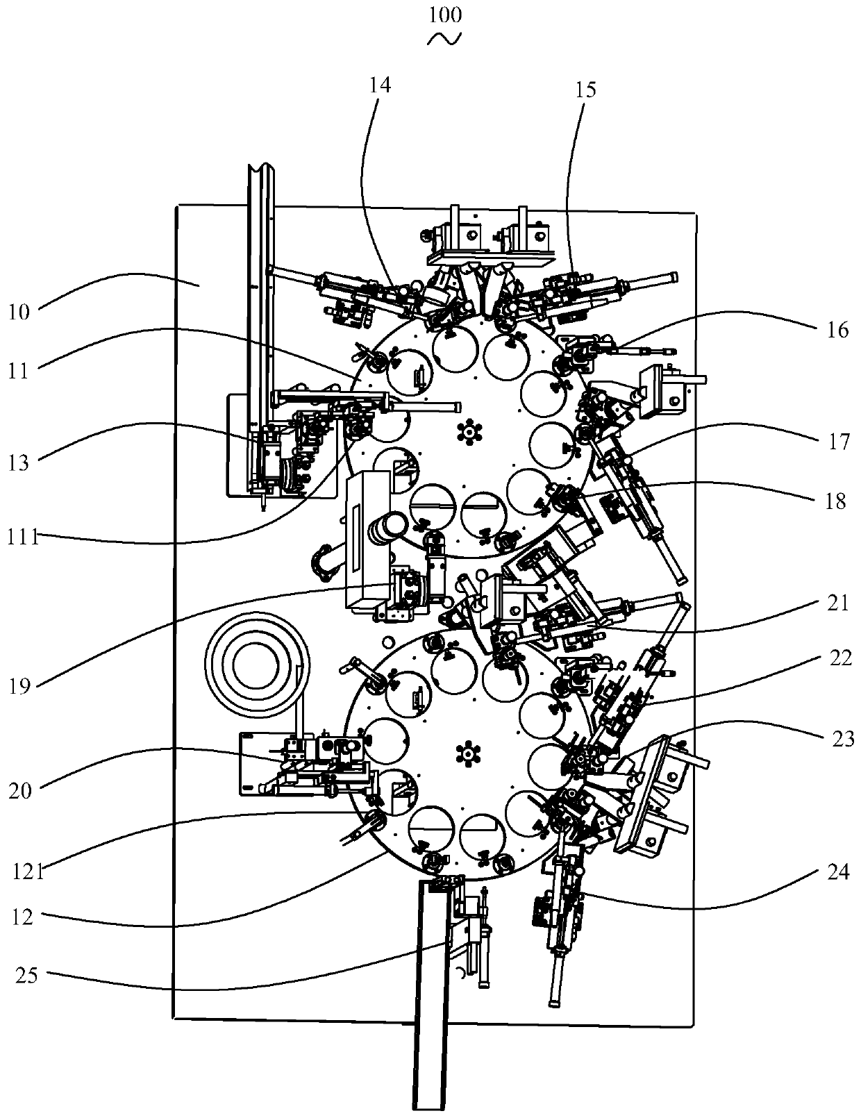
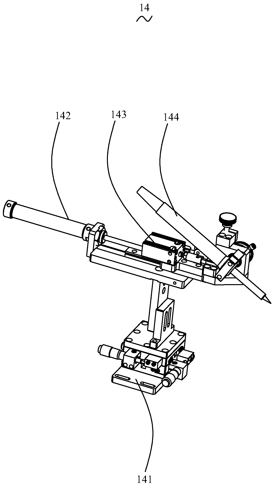
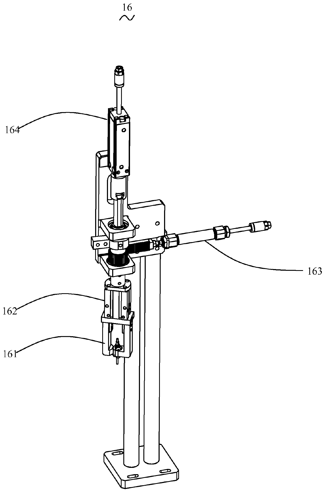
The invention relates to a full-automatic welding machine for dual-rotation-disc motor rotors. The machine comprises a workbench, a first rotation disc, a second rotation disc, a clamp rotor mechanism, a first welding mechanism, a second welding mechanism, a first positioning mechanism, a third welding mechanism, a resistance value testing mechanism, an overturning mechanism, a pressure sensor taking mechanism, a fourth welding mechanism, a fifth welding mechanism, a second positioning mechanism, a six welding mechanism and a finished product discharging mechanism. The first rotation disc andthe second rotation disc are arranged on the workbench. The clamp rotor mechanism, the first welding mechanism, the second welding mechanism, the first positioning mechanism, the third welding mechanism and the resistance value testing mechanism are arranged round the first rotation disc in sequence. The overturning mechanism is arranged between the first rotation disc and the second rotation disc. The pressure sensor taking mechanism, the fourth welding mechanism, the fifth welding mechanism, the second positioning mechanism, the six welding mechanism and the finished product discharging mechanism are arranged around the second rotation disc in sequence. Compared with the prior art, the full-automatic welding machine for the dual-rotation-disc motor rotor has the advantages that a dual-rotation-disc structure is adopted for driving the motor rotors to move, the motor rotors are tested and welded step by step in sequence, overheating can be avoided, the performance of the motor rotorsis prevented from being influenced, full-process automatic control is achieved, the efficiency and rate of finished products are improved, and the labor cost is reduced.

Description

【Technical field】 [0001] The invention relates to the technical field of motor assembly, in particular to a fully automatic welding machine for a double-turntable motor rotor. 【Background technique】 [0002] The fixed part of the motor is called the stator (stator), on which a pair of stationary main poles of DC excitation are installed; the rotating part (rotor-rotor) is called the armature core, and the armature winding is installed on it. After electrification, induced electromotive force is generated, which acts as a rotating magnetic field. After that, electromagnetic torque is generated for energy conversion. According to the shape of the stator winding and the way of embedded installation, the stator winding can be divided into two types: centralized and distributed according to the shape of the coil winding and the way of embedded wiring. [0003] In the assembly process of the motor stator, it is necessary to first weld the motor rotor wire end and the motor rotor ...

Claims


Application Information

Patent Timeline
Patent Type & Authority Applications(China)
IPC IPC(8): B23K3/00B23K3/08B23K101/36
CPCB23K3/00B23K3/08B23K3/087B23K2101/36
Inventor 曾赞杨银伟雄徐东明
Owner 深圳市鑫科德自动化有限公司
Why Eureka
Try Eureka