Burr machining equipment for plastic shell of storage battery

A technology for processing equipment and batteries, applied in metal processing equipment, grinding/polishing equipment, manufacturing tools, etc., can solve the problems of reducing the fine finish of deburring work, unable to fix the positioning of the battery shell, etc., to improve the fast release effect, Easy and precise cutting, high degree of automation effect

Active Publication Date: 2020-05-19
湖南省金翼有色金属综合回收有限公司
View PDF12 Cites 4 Cited by
  • Summary
  • Abstract
  • Description
  • Claims
  • Application Information

AI Technical Summary

Problems solved by technology

[0005] The purpose of the present invention is to address the deficiencies of the prior art, by setting a turnover mechanism to drive the clamping mechanism to perform turnover work, and to automatically switch functions, the clamping mechanism cooperates with the upper loading mechanism to realize the automatic loading of the battery case, and when clamping After positioning, the automatic hair removal process is carried out by the cutting mechanism, and then the clamping mechanism is used to cooperate with the discharge mechanism to complete the automatic output of the battery case, thereby solving the problem that the battery case cannot be fixed and positioned during the deburring work, thereby reducing the need for deburring. Technical Issues of Finishing of Rough Work

Method used


Image

  • Burr machining equipment for plastic shell of storage battery
  • Burr machining equipment for plastic shell of storage battery
  • Burr machining equipment for plastic shell of storage battery

Examples


Embodiment 1

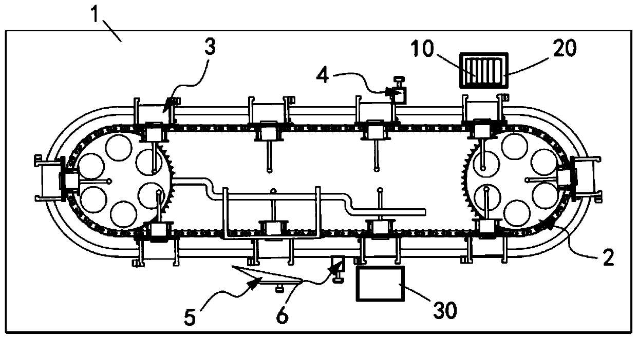
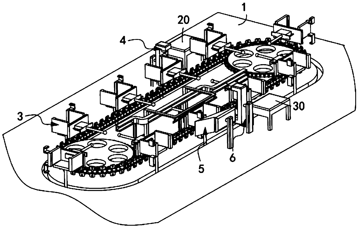
[0074] Such as figure 1 , figure 2 As shown in the figure, a battery plastic case burr processing equipment includes a frame 1, a turnover mechanism 2 installed on the frame 1, and several sets of clamping mechanisms 3 equidistantly arranged along the transmission direction of the turnover mechanism 2;

[0075] The frame 1 is provided with an upper loading station 4a, a cutting station 5a, and a discharging station 6a in sequence along the rotation direction of the turnover mechanism 2, and the upper loading station 4a is provided with an upper loading mechanism 4, and the cutter The position 5a is provided with a cutting mechanism 5, and the discharge station 6a is provided with a discharge mechanism 6;

[0076] The battery case 10 is uploaded from the loading station 4a to the clamping mechanism 3 through the loading mechanism 4, enters the cutting station 5a driven by the turnover mechanism 2, and completes the burr processing work through the cutting mechanism 5, and the...

Embodiment 2

[0122] Such as Figure 17 , Figure 18 As shown, the components that are the same as or corresponding to those in the first embodiment are marked with the corresponding reference numerals in the first embodiment. For the sake of simplicity, only the differences from the first embodiment will be described below. The difference between this embodiment two and embodiment one is:

[0123] further, such as Figure 17 , Figure 18 As shown, the horizontal pushing assembly 51 includes:

[0124] A pushing member 511, the pushing member 511 includes a push plate 5111, a support 5112 fixed to the outside of the push plate 5111 and two sets of telescopic units c5113 connecting the support 5112 and the outside of the side plate 315, and the side plate 315 is provided with a sliding groove 5114, the push plate 5111 is matched and slidably arranged in the sliding groove 5114; and

[0125] The guide rail 512, the guide rail 512 includes a first horizontal part 5121, a second horizontal ...


PUM


Abstract

The invention relates to burr machining equipment for a plastic shell of a storage battery. The burr machining equipment for the plastic shell of the storage battery comprises a rack, a turnover mechanism installed on the rack, and a plurality of groups of clamping mechanisms which are equidistantly arranged in a transmission direction of the turnover mechanism, wherein a loading station, a cutting station and a discharge station are sequentially formed on the rack in a rotation direction of the turnover mechanism, a loading mechanism is arranged on the loading station, a cutting mechanism isarranged on the cutting station, and a discharge mechanism is arranged on the discharge station; and a shell body of the storage battery is loaded to the clamping mechanisms from the loading station through the loading mechanism, enter the cutting station under the driving of the turnover mechanism and is subjected to burr treatment working through the cutting mechanism, and then is transmitted tothe discharge station through the driving of the turnover mechanism, and meanwhile, automatic output is carried out by virtue of the discharge mechanism. According to the burr machining equipment forthe plastic shell of the storage battery, the technical problem that fixing location cannot be carried out on the shell body of the storage battery during deburring working, and then the accuracy ofthe deburring working is lowered, is solved.

Description

technical field [0001] The invention relates to the technical field of storage battery casings, in particular to equipment for processing rough edges of plastic casings of storage batteries. Background technique [0002] The frame and ribs of the lead-acid battery grid often have certain burrs during the manufacturing process. The burrs are attached to the surface of the grid and it is difficult to remove them. After the plate is filled, the paste is missing, the grid is exposed, and the double-sided coating effect of the plate is poor. During the battery cycle, especially the positive plate is more likely to cause the active material to fall off, which affects the performance of the battery; large grid burrs may also cause the plate The machine is stuck during the coating process, and if the burrs of the four frames of the grid are entrained into the plate, it may even pierce the separator and cause an internal short circuit of the battery, which seriously affects the quali...

Claims


Application Information

Patent Timeline
Patent Type & Authority Applications(China)
IPC IPC(8): B24B9/20B24B41/00B24B41/06B24B47/20
CPCB24B9/20B24B41/005B24B41/06B24B47/20
Inventor 周杰
Owner 湖南省金翼有色金属综合回收有限公司
Why Eureka
Try Eureka