
Efficient overturning chip detection and positioning device

A chip detection and positioning device technology, applied in the direction of workpiece clamping devices, manufacturing tools, etc., can solve the problems of increasing time cost and low chip work efficiency, and achieve the effect of reducing time cost and improving work efficiency

Inactive Publication Date: 2020-05-19
佛山普瑞威尔科技有限公司
View PDF5 Cites 1 Cited by
  • Summary
  • Abstract
  • Description
  • Claims
  • Application Information

AI Technical Summary

Problems solved by technology

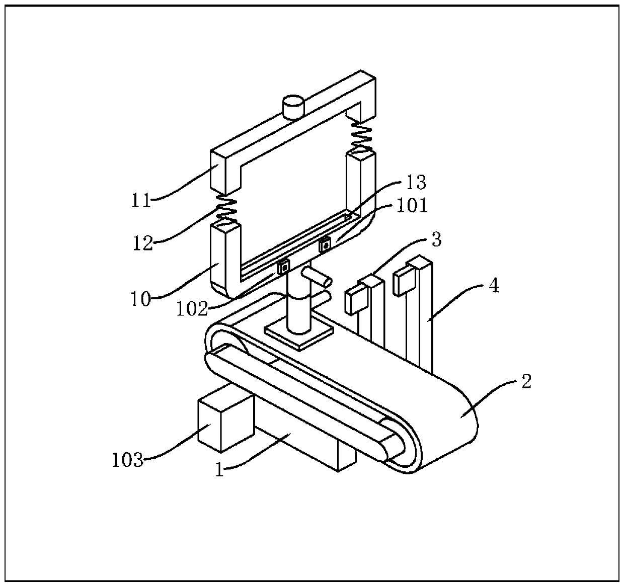
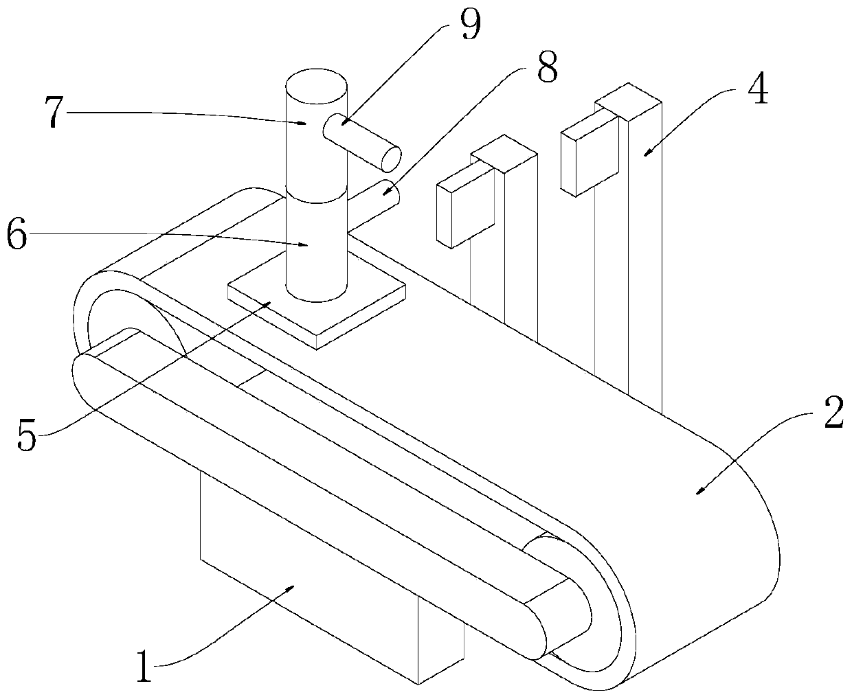
[0004] The purpose of the present invention is to solve the problem of low work efficiency and increased time cost in the prior art of manual flipping of chips by staff, and propose a high-efficiency flipping chip detection and positioning device

Method used


Image

  • Efficient overturning chip detection and positioning device
  • Efficient overturning chip detection and positioning device
  • Efficient overturning chip detection and positioning device

Examples


Embodiment Construction

[0021] The following will clearly and completely describe the technical solutions in the embodiments of the present invention with reference to the accompanying drawings in the embodiments of the present invention. Obviously, the described embodiments are only some, not all, embodiments of the present invention.

[0022] In describing the present invention, it should be understood that the terms "upper", "lower", "front", "rear", "left", "right", "top", "bottom", "inner", " The orientation or positional relationship indicated by "outside", etc. is based on the orientation or positional relationship shown in the drawings, and is only for the convenience of describing the present invention and simplifying the description, rather than indicating or implying that the referred device or element must have a specific orientation, so as to Specific orientation configurations and operations, therefore, are not to be construed as limitations on the invention.

[0023] refer to Figure ...


PUM


Abstract

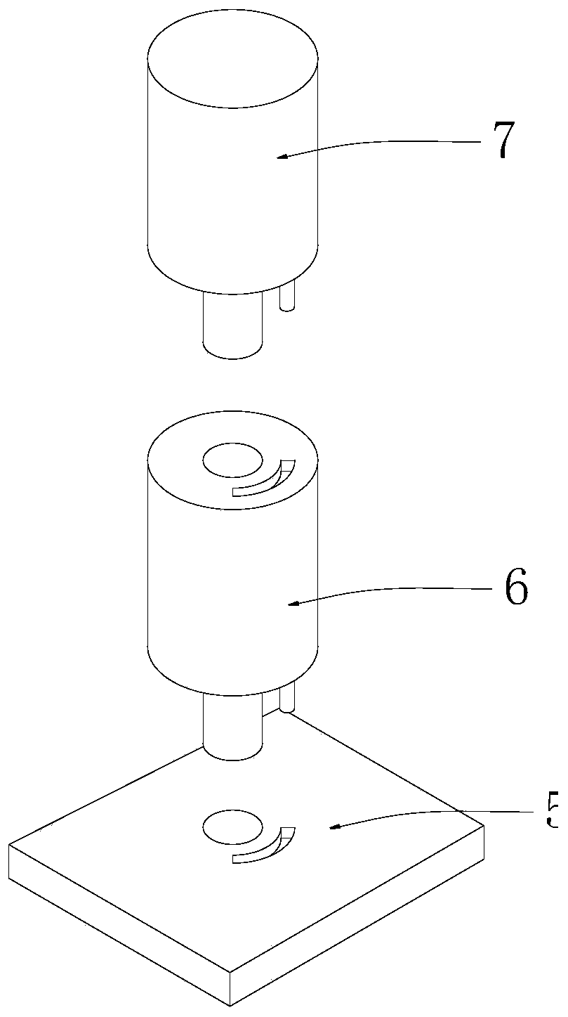
The invention discloses an efficient overturning chip detection and positioning device and belongs to the technical field of chips. The efficient overturning chip detection and positioning device comprises a support. A belt, a first baffle and a second baffle are arranged on the support. A connecting plate is arranged on the belt, and a first rotating pillar is arranged on the connecting plate. Asecond rotating pillar is arranged on the first rotating pillar. A first long rod and a second long rod are arranged on the first rotating pillar and the second rotating pillar correspondingly. A holding frame is arranged on the top of the second rotating pillar, and a clamping bar is arranged on the holding frame. By means of the efficient overturning chip detection and positioning device, the first rotating pillar can rotate to drive the second rotating pillar to rotate, the second rotating pillar can rotate further so as to drive the holding frame and the clamping bar to rotate, due to twotimes of rotation, the chips fixed to the holding frame and the clamping bar can be overturned, the overturning purpose is achieved, the work efficiency of personnel is improved, and the time cost isreduced.

Description

technical field [0001] The invention relates to the technical field of chip technology, in particular to an efficient flip chip detection and positioning device. Background technique [0002] The MCU in the chip is a single-chip microcomputer, which also includes various components such as resistors or capacitors to form a chip. The reverse side can be a metal terminal, a burning point, and the metal terminal is used to contact the device and communicate with it. For example, the chip is installed on the After the printer powder box, it can communicate with the printer. The burning point is a separately set point. It can contact the burning point through the burning device to carry out the burning program. The chip can only be programmed after the MCU is burned into the program. , to perform a certain function. [0003] Some chips need flipping detection after programming. The existing detection method is not suitable for flipping the chip. The flipping process is manual, w...

Claims


Application Information

Patent Timeline
Patent Type & Authority Applications(China)
IPC IPC(8): B25B11/00
CPCB25B11/00
Inventor 周露露张凯
Owner 佛山普瑞威尔科技有限公司
Learn More