Speed amplification combined damping device and eddy current damping wall

A technology of eddy current damping and damping devices, which is applied in building types, building components, and earthquake resistance, can solve the problems of small displacement between building floors and increase energy consumption efficiency of damping walls, and achieve the effect of increasing energy consumption efficiency

Inactive Publication Date: 2020-11-24
HUNAN UNIV
View PDF6 Cites 3 Cited by
  • Summary
  • Abstract
  • Description
  • Claims
  • Application Information

AI Technical Summary

Problems solved by technology

[0011] The purpose of the present invention is to provide a speed reduction method for the design and manufacture of large-tonnage damping walls that are still difficult to solve the problem of large-tonnage damping walls with a single displacement or speed amplification method under the influence of wind

Method used


Image

  • Speed amplification combined damping device and eddy current damping wall
  • Speed amplification combined damping device and eddy current damping wall
  • Speed amplification combined damping device and eddy current damping wall

Examples


Embodiment 1

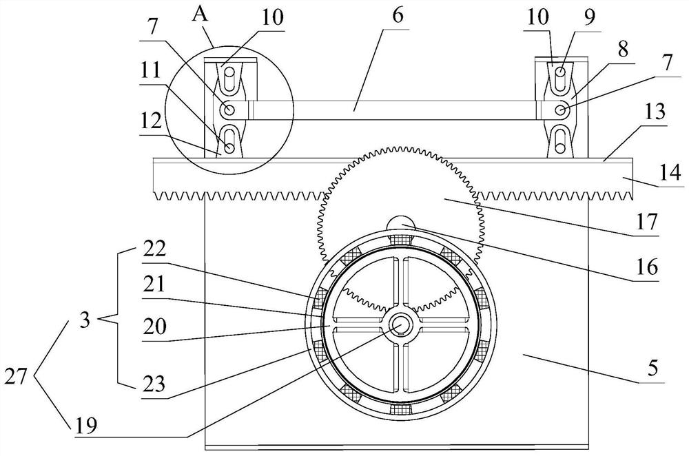
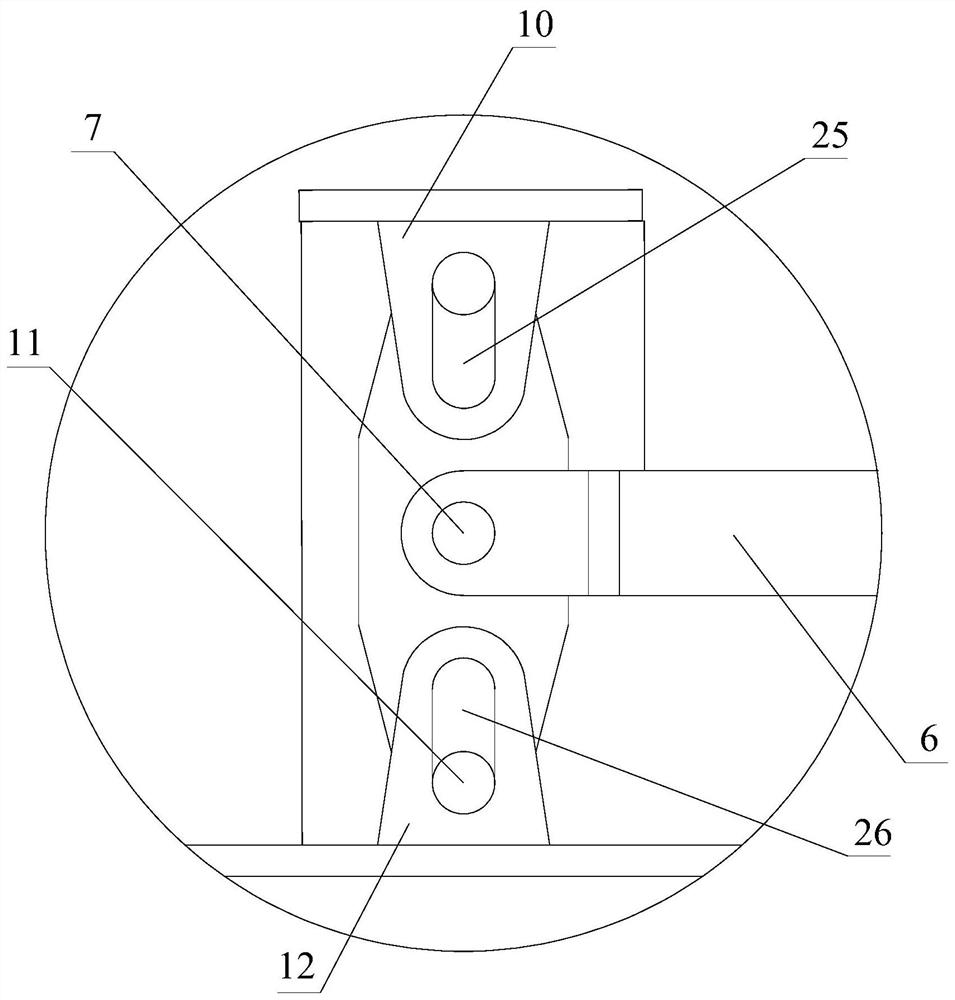
[0063] Such as Figure 1-3 As shown, a speed amplification combined damping device described in this embodiment includes,

[0064] The rigid support 5 includes two vertically arranged side plates 2, and at least two first supports 10 are arranged at intervals on the upper part of the rigid support 5, and each first support 10 is vertically provided with a first strip shaped hole 25;

[0065] The rack 14 is arranged horizontally, and the back of the rack 14 is connected with a rack stiffening plate 13 on the side away from the teeth, and at least two second supports 12 are arranged at intervals along the length direction of the rack 14 on the rack stiffening plate 13 , each second support 12 is vertically provided with a second strip-shaped hole 26, the position of the second strip-shaped hole 26 corresponds to the position of the first support 10, and the number corresponds one by one;

[0066] The first gear 15 meshes with the rack 14;

[0067] There are at least two lever...

Embodiment 2

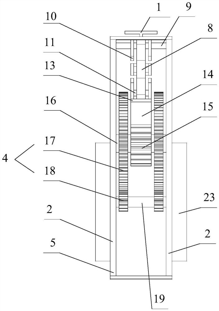
[0093] Such as Figure 4 As shown, an eddy current damping wall with a speed amplification combined damping device described in this embodiment includes a superstructure 1 and a lower building structure 24, and also includes a speed amplification combined damping device as described in Embodiment 1 , the superstructure 1 is connected to the connector 6 , and the substructure 24 is connected to the rigid support 5 .

[0094] The lower building structure 24 is generally a floor or beam below the rigid support 5; the superstructure 1 is generally a floor or beam above the connector 6;

[0095] When in use, the lower building structure 24 is connected with the rigid support 5 for supporting the rigid support 5, and connecting the superstructure 1 with the connecting piece 6, so that the connecting piece 6 can connect the superstructure 1 The motion of the rack is converted into the motion of the rack 14 after being accelerated, and then further accelerated by the speed-increasing...


PUM


Abstract

The invention relates to the field of buildings, in particular to a speed amplification combined damping device and an eddy current damping wall. The speed amplification combined damping device comprises a rigid support, a rack, a first gear, levers, at least one stage of overdrive gear assembly and an eddy current damping assembly, wherein the rack is horizontally arranged, the first gear is meshed with the rack, one end of each lever is rotationally connected with the rigid support, the other end of each lever is rotationally connected with the rack, a connecting piece is hinged between every two adjacent levers, the connecting pieces are hinged to the levers through hinge shafts, the hinge shafts are located between first rotating shafts and second rotating shafts, the connecting piecescan drive the rack to be in meshing transmission with the first gear, the eddy current damping assembly is connected with the rigid support, and the overdrive gear assembly can drive the eddy currentdamping assembly to generate damping force. According to the speed amplification combined damping device, design and manufacturing of a large-tonnage damping wall can be achieved in a composite acceleration mode, the multiple speed amplification effect is achieved, and the energy consumption efficiency of the damping wall is improved.

Description

technical field [0001] The invention relates to the construction field, in particular to a speed amplification combined damping device and an eddy current damping wall. Background technique [0002] Under the action of wind and earthquake loads, the building will vibrate greatly, which will affect the safety and durability of the building. At present, structural vibration control has become the mainstream measure to reduce building vibration (vibration). In the field of structural vibration control, the damping wall is a passive energy dissipation and vibration reduction component, which is installed between building floors as a wall, and uses the relative movement between building floors to increase the damping of the structure to achieve energy dissipation and shock absorption. Compared with other energy dissipation and shock absorbing devices, the damping wall has the following advantages: [0003] (1) Easy to manufacture and install without complicated devices; [000...

Claims


Application Information

Patent Timeline
IPC IPC(8): E04B1/98E04H9/02
CPCE04B1/98E04H9/021E04H9/023E04H9/027
Inventor 李寿英李亚峰毛伟阳陈政清
Owner HUNAN UNIV
Why Eureka
Try Eureka