Tool for compression molding of carbon fiber rectangular cross section thin-wall pipe fitting

A compression molding technology with a rectangular cross-section, which is applied in the direction of tubular objects, other household appliances, household appliances, etc., can solve the difficulties of stacking prepreg layers, rectangular cross-section thin-walled tubes, and the inability to ensure the smoothness of the inner and outer walls of the product and the smoothness of the wall. Uniform thickness and other issues, to achieve the effect of excellent rigidity, high pressure and uniform wall thickness

Inactive Publication Date: 2020-05-19
AVIC COMPOSITES
View PDF2 Cites 3 Cited by
  • Summary
  • Abstract
  • Description
  • Claims
  • Application Information

AI Technical Summary

Problems solved by technology

[0003] Since the elongation direction of the fork finger parts is a variable cross-section, the inner and outer surfaces are required to be smooth, and the outer contour size and wall thickness of the parts are strictly required, so it is impossible to guarantee the smoothness of the inner and outer walls of the parts by thermal expansion process or air expansion process. and uniform wall thickness
However, in the production practice of using the molding process to manufacture such rectangular cross-section thin-walled pipe fittings, since the prepreg thickness before curing is greater than the thickness after curing, the steel core cannot be inserted smoothly. will cause stacking of prepreg layups
At the same time, the molding process can effectively pressurize the upper and lower sides of the pipe fittings, but it cannot effectively pressurize the two side walls. These problems have brought great difficulties to the use of the molding process to manufacture rectangular cross-section thin-walled pipes.

Method used


Image

  • Tool for compression molding of carbon fiber rectangular cross section thin-wall pipe fitting
  • Tool for compression molding of carbon fiber rectangular cross section thin-wall pipe fitting
  • Tool for compression molding of carbon fiber rectangular cross section thin-wall pipe fitting

Examples


Embodiment Construction

[0025] The present invention will be further described below in conjunction with the accompanying drawings and embodiments.

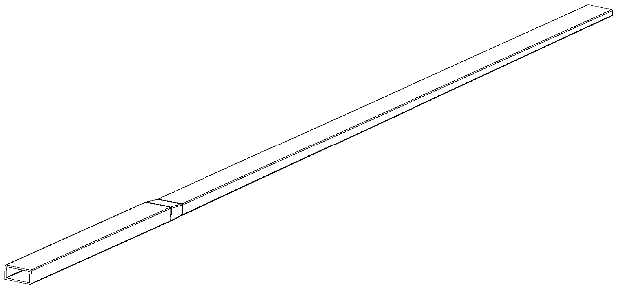
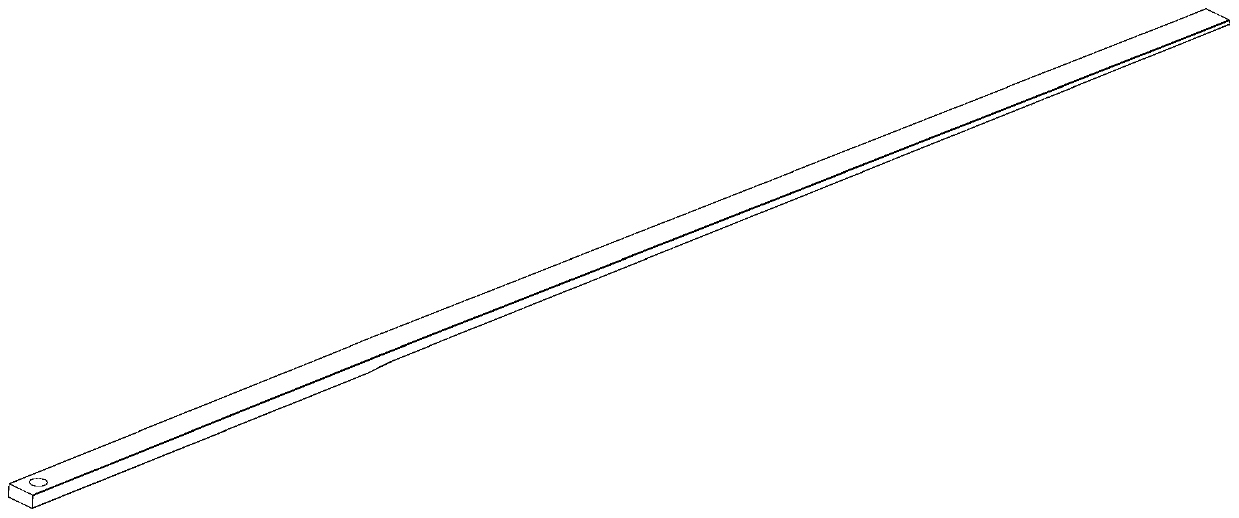
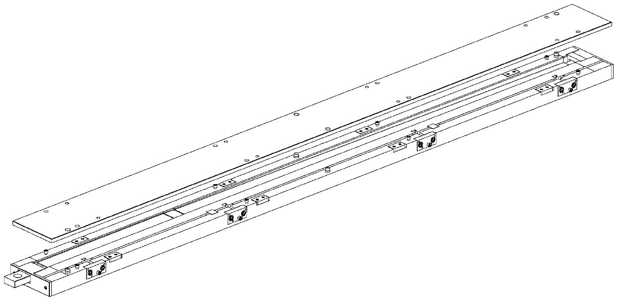
[0026] See attached Figure 1~5 As shown, the steps of adopting the tooling of the present invention to prepare a rectangular cross-section thin-walled pipe fitting are as follows:

[0027] Step 1. Assemble the mold, and move the movable block 5 to the mold cavity by rotating the screw 7 until the lower stop of the movable block 5 contacts the resting surface at the bottom of the cavity of the female mold 1, and determine the position of the movable block 5 ;

[0028] Step 2, cleaning the female mold 1 cavity and applying a release agent;

[0029] Step 3: Spread the carbon fiber prepreg layer by layer in the cavity of the female mold 1, and spread the carbon fiber cloth layer higher than the cavity on the parting surfaces on both sides of the mold;

[0030] Step 4: Compact the ply by bag pressing;

[0031] Step 5, by rotating the screw 7 to slightly...


PUM


Abstract

The invention discloses a tool for compression molding of a carbon fiber rectangular cross section thin-wall pipe fitting. The tool comprises a female die (1) and a male die (2), wherein a cavity forpaving and pasting prepreg (4) is formed in the female die (1); a movable block (5) forms one side wall of the cavity and can move along the direction perpendicular to the side wall to change the transverse width size of the cavity, so that a steel core (3) can be conveniently placed; and in addition, a silicone rubber layer (6) is arranged on the outer side of the movable block (5) and is heatedto expand to apply pressure to the movable block (5) to further apply pressure to the side wall of the rectangular cross section thin-wall pipe fitting. The tool solves the problems that thermal expansion or air bulking formation carried out in the rectangular cross section thin-wall pipe fitting causes that the inner wall of the pipe fitting is not smooth and the wall thickness of the pipe fitting is not uniform, adoption of a fixed die cavity die causes that the steel core cannot be smoothly placed after laying carbon fiber cloth layers, and the moulding process cannot compress the side wall, parallel with the compressing direction, in the rectangular cross section pipe fitting.

Description

technical field [0001] The invention relates to a press-molded tooling for a thin-walled pipe fitting with a rectangular cross-section of carbon fiber, which belongs to the technical field of composite material molding. Background technique [0002] The fork finger is a part installed on the manipulator and used as the support structure of the picker. It is a piece with a length of about 2300mm. In the length direction, the section side length gradually decreases from 60×30mm to 56×12mm, and the wall thickness is about 1.2mm. Thin-walled hollow tubes of rectangular cross-section. [0003] Since the elongation direction of the fork finger parts is a variable cross-section, the inner and outer surfaces are required to be smooth, and the outer contour size and wall thickness of the parts are strictly required, so it is impossible to guarantee the smoothness of the inner and outer walls of the parts by thermal expansion process or air expansion process. and uniform wall thickne...

Claims


Application Information

Patent Timeline
Patent Type & Authority Applications(China)
IPC IPC(8): B29C70/34B29C70/54B29L23/00
CPCB29C70/345B29C70/54B29L2023/22B29C70/461
Inventor 丁晓春孙树凯王洋
Owner AVIC COMPOSITES
Why Eureka
Try Eureka