Spring conveying roller, combined conveying roller, grooved roller and conveying assembly

A technology of conveying rollers and grooved rollers, which is applied in the field of spring conveying rollers, combined conveying rollers, grooved rollers and conveying components formed by them, which can solve the problems of inconvenient processing and inconvenient collection of materials, and achieve stable pleats, long lasting effect

Pending Publication Date: 2020-05-19
WENZHOU KEWANG MACHINERY
View PDF0 Cites 0 Cited by
  • Summary
  • Abstract
  • Description
  • Claims
  • Application Information

AI Technical Summary

Problems solved by technology

[0003] In the field of packaging machinery transportation such as woven bags and plastic bags, and machinery with transportation material stations such as paper cutters, due to the thin thickness of the materials to be conveyed (such as printing paper with a thickness of less than 1mm, packaging bags, inner membranes of woven bags, Woven bag body, etc.), high softness, so during the conveying process, because the conveying components are usually conveyed by two conveying rollers with clearance fit and oppositely arranged, the material between the front and rear conveying positions often sags Especially on the outlet side of the material, the material is also easy to fit the outer circle of the roller and fall, which is not convenient for further processing in the subsequent process, nor is it convenient for collecting the material

Method used


Image

  • Spring conveying roller, combined conveying roller, grooved roller and conveying assembly
  • Spring conveying roller, combined conveying roller, grooved roller and conveying assembly
  • Spring conveying roller, combined conveying roller, grooved roller and conveying assembly

Examples


Embodiment 1

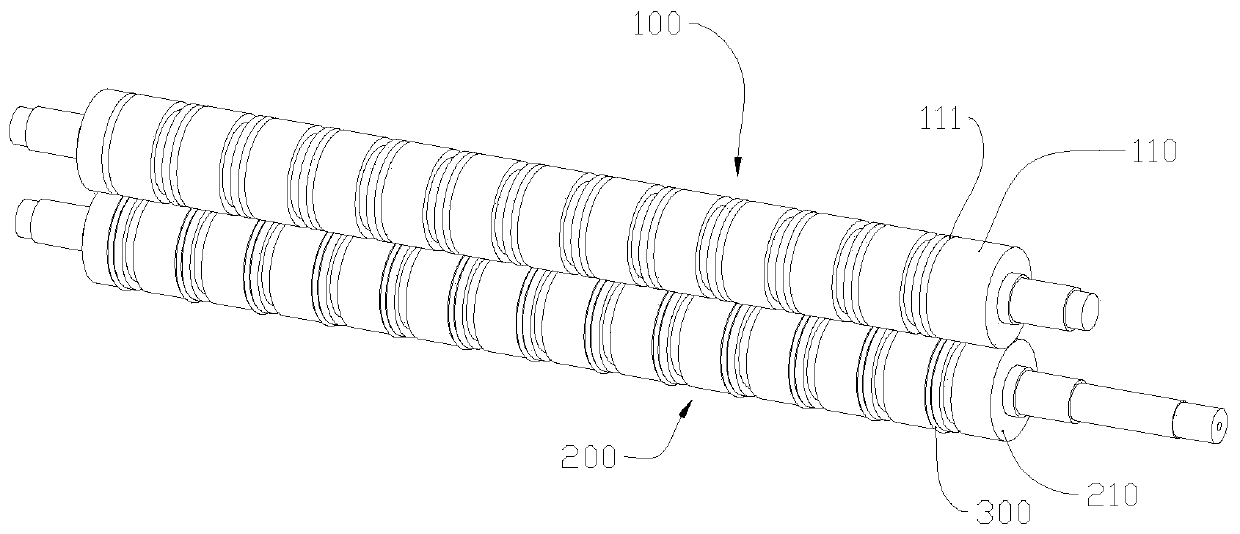
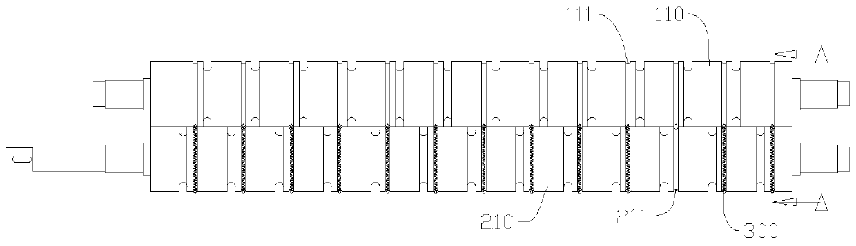
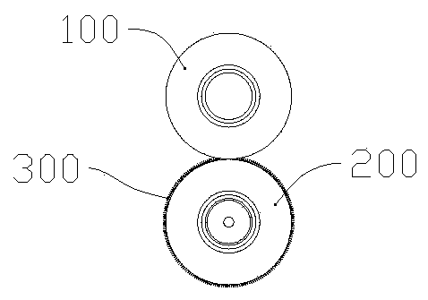
[0046] Embodiment 1 refers to figure 1 The structure of a spring conveying roller 100 shown in , includes a cylindrical roller body 110 and transmission shafts arranged on both end faces of the roller body 110, and the outer surface of the roller body 110 is provided with a plurality of first grooves 111, the second A groove 111 is an annular groove, which is arranged around the roller body 110 parallel to the radial plane of the roller body 110. The first groove 111 is provided with a spring bar 300 that coincides with the path of the first groove 111. The accompanying drawings figure 1 Restricted by the level of drawing, a hollow tube is used to replace the indicator spring bar 300, and it is best to combine Figure 2-Figure 4 To understand the spring bar 300 in , in addition, subject to drawing level and for the purpose of clearer presentation, Figure 2-Figure 4 The spring bar 300 in the figure has been simplified—it is shown in the form of a single line. In fact, the spr...

Embodiment 2

[0051] Embodiment 2 The difference between this embodiment and Embodiment 1 is that the ring groove is arranged on or inclined to the radial plane of the roller body 110, that is, in this embodiment, the first groove 111 is an inclined groove, correspondingly, The first groove 111 in the first embodiment is a straight groove.

Embodiment 3

[0052] Embodiment 3 The difference between this embodiment and the above embodiments is that the first groove 111 is a spiral groove, which is used to protrude the effect of the spring bar 300 . The number of spiral grooves is preferably more than two and distributed in parallel. However, under parallel distribution, in order to make the roller body 110 rotate and convey the material 400, it is best to maintain the same force on the material 400 each time it passes. Spacing, try to make the spiral groove evenly distributed.


PUM


Abstract

The invention belongs to the field of conveying equipment, and discloses a spring conveying roller, a combined conveying assembly, a grooved roller and a conveying assembly. The spring conveying roller comprises a columnar roller body and transmission shafts arranged on the two end faces of the roller body, grooves are formed in the outer surface of the roller body and surround the roller body, spring strips coinciding with the paths of the grooves are arranged in the grooves, the surfaces of the spring strips protrude out of the surface of the roller body, the first grooves and second grooveswhich correspond in position are formed in the surface of the spring conveying roller and the surface of the grooved roller, the spring strips are arranged in the first grooves, the spring strips canbe embedded into the second grooves when the spring conveying roller and the grooved roller are used in cooperation, by means of the concave-convex relation and the acting force relation between thespring strips and the second grooves, the rigidity of materials and the clamping force of the conveying assembly on the materials are improved.

Description

technical field [0001] The invention relates to the field of mechanical conveying rollers, in particular to a spring conveying roller, a combined conveying roller, a grooved roller and a conveying assembly formed using the same. Background technique [0002] Roller is a cylindrical part, divided into driving and driven rollers, which are widely used in various transmission systems such as rotary screen printing machines, digital printers, mining conveying equipment, papermaking and packaging machinery. Rubber roller is one of them, which is a roller-shaped product made of metal or other materials as the core and covered with rubber through vulcanization. [0003] In the field of packaging machinery transportation such as woven bags and plastic bags, and machinery with transportation material stations such as paper cutters, due to the thin thickness of the materials to be conveyed (such as printing paper with a thickness of less than 1mm, packaging bags, inner membranes of wo...

Claims


Application Information

Patent Timeline
Patent Type & Authority Applications(China)
IPC IPC(8): B65H5/06
CPCB65H5/062B65H2404/141B65H2404/1415B65H2404/19
Inventor 郭矛邱述展
Owner WENZHOU KEWANG MACHINERY
Why Eureka
Try Eureka