
High-pressure container protection structure

A technology of protective structure and protective frame, which is applied to the installation device of container structure, container filling method, container discharge method, etc., can solve the problem of isolation of inoperable personnel from products and high-pressure gas cylinder groups, leakage and high-speed ejection, personnel Equipment damage and other problems, to achieve the effect of stable protective structure, impact resistance, high and low temperature stability

Inactive Publication Date: 2020-05-19
中国人民解放军96962部队
View PDF7 Cites 0 Cited by
  • Summary
  • Abstract
  • Description
  • Claims
  • Application Information

AI Technical Summary

Problems solved by technology

[0004] At present, the test work is carried out in the factory building. Due to the limitation of the site conditions, it is impossible to isolate the operators from the product and the high-pressure gas cylinder group on site.
During the test, there are mainly three types of safety hazards: one is the damage to personnel and equipment caused by the accidental disengagement of the stainless steel high-pressure corrugated pipeline. The air pressure in the inflation pipeline can be as high as 30MPa. If the reliable connection causes disengagement, the connecting pipeline will swing violently and freely under the action of high-pressure gas, which is very easy to cause injury to the on-site personnel; the second is the personal injury caused by the gas leakage and high-speed ejection caused by the accidental disconnection of the pipeline, and the internal storage of the product The air tank stores compressed air with a pressure of up to 30MPa. If the pipeline is accidentally disconnected during the test, the compressed air in the air tank will leak and be sprayed out at a high speed (30MPa pressure difference, the air velocity at the leak can reach up to 707m / s), If there is no corresponding isolation and protection facility, certain injuries will be caused to the on-site personnel; the third is the personnel injury caused by the high-pressure and high-speed compressed air ejected from the nozzle during the equipment function test. During the system function test, the spherical (or ring) cylinder in the product The stored 30MPa compressed air will be ejected from 12 nozzles (1MPa pressure difference, the air velocity at the nozzle can reach up to 435m / s instantaneously). Once the gas is accidentally released when people approach, it will cause serious injury to the personnel on site

Method used


Image

  • High-pressure container protection structure
  • High-pressure container protection structure
  • High-pressure container protection structure

Examples


Embodiment Construction

[0023] The following examples can enable those skilled in the art to understand the present invention more fully, but do not limit the present invention in any way.

[0024] The invention adopts a movable and assembled isolation protection room, including an isolation protection frame and a movable shield structure. The isolation frame can be a shelf to form a room, and then the movable shield structure can be mounted on the isolation frame in a suitable manner. In the present invention, the isolation protection frame can be any suitable structure capable of installing a movable shield structure, which will not be described in detail here.

[0025] In some embodiments, the shield structure has a height less than 1.6m and a width greater than or equal to 0.9m. In some embodiments, the nozzle is protected by a movable shield, which can isolate the nozzle from the staff. On the one hand, the operator is prevented from being hurt by the high-pressure gas ejected from the nozzle, ...


PUM

PropertyMeasurementUnit
heightaaaaaaaaaa
widthaaaaaaaaaa
glass transition temperatureaaaaaaaaaa

Abstract

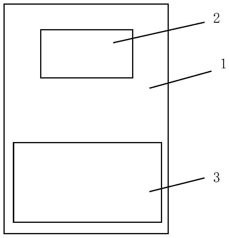
The invention provides a protection structure. The protection structure comprises a protection frame and a shield structure arranged on the protection frame. The shield structure comprises a window and a metal net area, the window is provided with bullet-proof glass, and the material of the shield structure is ultra-high molecular weight polyethylene. The protection structure is stable, the material performance is excellent, and the purpose of protection can be well achieved.

Description

technical field [0001] The invention relates to the field of protection and safety, more specifically, to a protection structure for a high-pressure vessel. Background technique [0002] At present, in the process of air tightness and functional test, two gas cylinder groups (3 gas cylinders in each group, each gas cylinder filled with 35MPa compressed air) are used as the gas source. The product is filled with 30MPa compressed air, and about 1MPa compressed air will be ejected from the product nozzle during the function test. [0003] According to the "Stationary Pressure Vessel Safety Technology Supervision Regulations" (TSG21-2016), according to the classification standard of working pressure, the pressure greater than 10MPa is high pressure, according to the classification standard of danger and hazard, the pressure vessel is a third-class pressure vessel, which belongs to the hazard The highest level of sex and danger. In the industrial sector, high-pressure container...

Claims


Application Information

Patent Timeline
Patent Type & Authority Applications(China)
IPC IPC(8): F17C13/08F17C13/00
CPCF17C13/00F17C13/08F17C2205/0153
Inventor 王红召李健王光辉刘展马龙关桢伏圣山王帮涵
Owner 中国人民解放军96962部队
Learn More