Energy-saving-type air cooler cooling system
A technology of cooling system and air cooler, applied in the direction of water shower cooler, heat exchanger type, direct contact heat exchanger, etc., can solve the problems of heat waste, high energy consumption, poor energy saving, etc., to reduce workload, Unique scheme and reasonable design effect
- Summary
- Abstract
- Description
- Claims
- Application Information
AI Technical Summary
Problems solved by technology
Method used
Image
Examples
Embodiment 1
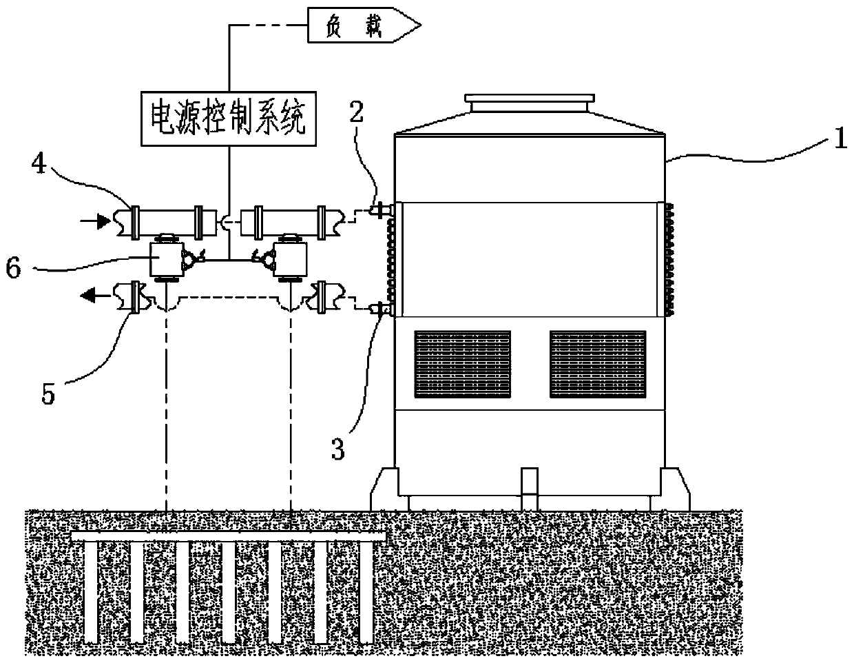
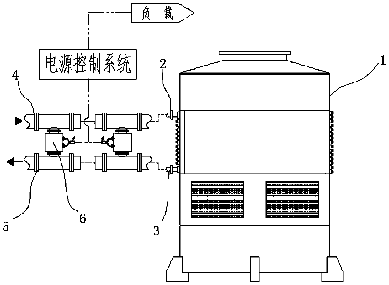
[0028] An energy-saving air cooler cooling system, comprising an air cooler 1, the air cooler 1 includes a fluid inlet 2 and a fluid outlet 3, the fluid inlet 2 communicates with a feed pipe 4 through a flange, and the fluid outlet 3 passes through a The blue is connected with the discharge pipeline 5, and it is characterized in that a thermoelectric generator 6 is arranged between the feed pipeline 4 and the ground or the discharge pipeline 5, and the thermoelectric generator 6 includes a hot end surface 7 and a cold end surface 8, so Both the hot end surface 7 and the cold end surface 8 are connected with a heat conduction member 9, the heat conduction member 9 on the hot end surface 7 is implanted in the feed pipe 4, and the heat conduction member 9 on the cold end surface 8 is implanted below the surface or in the discharge pipeline within 5;
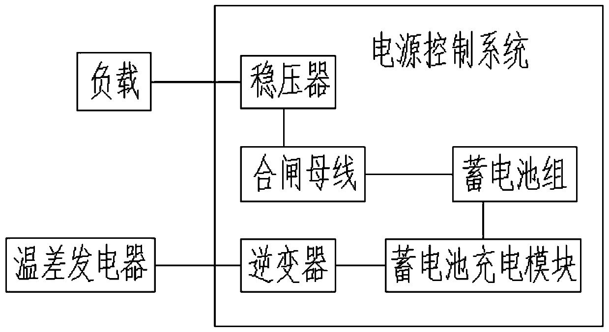
[0029] The power output terminal 10 of the thermoelectric generator 6 interacts with the power control system, and supplies power ...
Embodiment 2
[0039] An energy-saving cooling system for an air cooler in this embodiment, wherein, the heat conduction member 9 implanted in the feed pipe 4 and the discharge pipe 5 is in the shape of a tube sleeve, and its outer wall is in contact with the feed pipe 4, The inner wall of the discharge pipe 5 is bonded;
[0040] Wherein, a plurality of heat conduction fins distributed in parallel are arranged in the middle tube sleeve formed by the heat conduction member 9 implanted in the feed pipe 4 and the discharge pipe 5;
[0041] The structure of the heat conduction element can effectively improve the heat conduction efficiency of the heat conduction element, increase and stabilize the temperature difference when the thermoelectric generator is working, and can also accelerate the heat dissipation of the high-temperature fluid itself, while having little influence on the flow of the fluid.
Embodiment 3
[0043] In the cooling system of an energy-saving air cooler in this embodiment, the heat conduction element 9 implanted in the feed pipe 4 and the discharge pipe 5 is cylindrical, and its outer wall is in contact with the feed pipe 4 and the discharge pipe 5 The inner wall of the heat conduction member 9 is provided with a plurality of heat conduction channels;
[0044] Wherein, a plurality of said heat conduction channels are distributed in a honeycomb type, and the axial direction is parallel to the axial direction of the feed pipe 4 and the discharge pipe 5;
[0045] The structure of the heat conduction element can effectively improve the heat conduction efficiency of the heat conduction element, but has a great influence on the flow of the fluid, and is suitable for the use of low flow rate fluid.
PUM
 Abstract
Description
Claims
Application Information
 - R&D
- Intellectual Property
- Life Sciences
- Materials
- Tech Scout
- Unparalleled Data Quality
- Higher Quality Content
- 60% Fewer Hallucinations
Browse by: Latest US Patents, China's latest patents, Technical Efficacy Thesaurus, Application Domain, Technology Topic, Popular Technical Reports.
© 2025 PatSnap. All rights reserved.Legal|Privacy policy|Modern Slavery Act Transparency Statement|Sitemap|About US| Contact US: help@patsnap.com


