Method for testing damage of star sensor detector caused by strong light irradiation

A star sensor and radiation damage technology, applied in the field of star sensors, can solve problems such as affecting the attitude measurement accuracy of the star sensor, insufficient complex lighting environment, system failure, etc.

Inactive Publication Date: 2020-05-19
SHANGHAI AEROSPACE CONTROL TECH INST
View PDF12 Cites 1 Cited by
  • Summary
  • Abstract
  • Description
  • Claims
  • Application Information

AI Technical Summary

Problems solved by technology

However, the research on the impact of complex lighting environments is not systematic enough, and sufficient experimental verification has not yet been carried out.
The photoelectric sensor works in a complex lighting environment, mainly for imaging small moving objects in space, and the background stray light has a serious impact
The impact of stray light on the system, if it is mild, will reduce the signal-to-noise ratio and contrast of the target, thus affecting the detection or identification capabilities of the entire system; target; or due to the uneven distribution of stray light on the image plane, a false signal is formed on the system detector, causing the system to detect a false target or even cause the entire system to fail, seriously affecting the attitude measurement accuracy of the star sensor

Method used


Image

  • Method for testing damage of star sensor detector caused by strong light irradiation
  • Method for testing damage of star sensor detector caused by strong light irradiation
  • Method for testing damage of star sensor detector caused by strong light irradiation

Examples


Embodiment 1

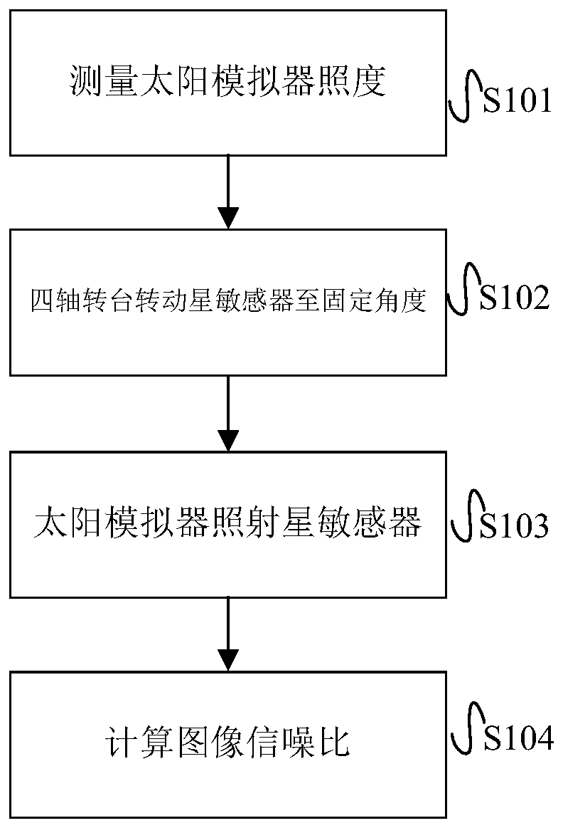
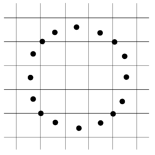
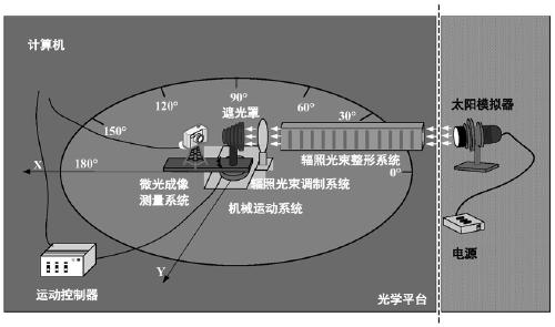
[0038] 1. Install the low-light imaging measurement system on a high-precision four-axis turntable, turn the turntable to a fixed position, and determine the angle between the optical axis between the solar simulator and the low-light imaging measurement system, so that the light emitted by the solar simulator can be fixed The angle is incident through the radiation beam shaping system, according to figure 2 At the point shown, rotate the four-axis turntable to measure the illuminance of the solar simulator at different points. Afterwards, the illuminance of the solar simulator is obtained by comprehensive calculation according to the illuminance of the solar simulator at different points, and the irradiance at the exit end of the solar simulator is measured.

[0039] 2. Install the star sensor on a high-precision four-axis turntable, and determine the angle between the optical axis between the solar simulator and the star sensor again, so that the light emitted by the solar ...

Embodiment 2

[0043] 1. Press image 3 As shown in , fix the low-light measurement system on the four-axis turntable, turn it at a certain angle, turn on the solar simulator, press figure 2 Rotate the four-axis turntable as shown to make the star sensor measure the illuminance of the solar simulator at different points, and calculate the illuminance of the solar simulator comprehensively according to the illuminance of the solar simulator at different points.

[0044] Two, press Figure 4 As shown, remove the low-light measurement system, install the star sensor, and make sure that the angle between the optical axis of the star sensor and the solar simulator is 5°.

[0045] 3. Turn on the solar simulator and irradiate the solar simulator for 5 minutes.

[0046] 4. Turn off the solar simulator and take a black picture of the star sensor, such as Figure 6 shown.

[0047] 5. Calculate the signal-to-noise ratio of the area irradiated by strong light in image 6. The signal-to-noise ratio in ...


PUM


Abstract

The invention discloses a method for testing damage of a star sensor detector caused by strong light irradiation. The utilizes a solar simulator to simulate a light source to irradiate the star sensordetector and comprises the following steps: (1) measuring the illuminance of the solar simulator to determine the illuminance of the solar simulator; (2) forming a specified included angle between the optical axis of the star sensor and the solar simulator; (3) irradiating the star sensor by the solar simulator; and (4) shooting by the star sensor detector to obtain an image, and determining thedamage degree of the detector after irradiation by utilizing the image signal-to-noise ratio of the image. The problem of how to measure the damage degree of the star sensor detector when the star sensor is irradiated in a complex illumination environment can be solved, and the damage degree of illumination of different incident angles to the star sensor detector can also be detected.

Description

technical field [0001] The invention relates to the technical field of star sensors, in particular to a method for testing star sensor detectors damaged by strong light irradiation. Background technique [0002] With the development of the aerospace industry, star sensors have been widely used in determining the attitude of spacecraft. The star sensor takes the star in the inertial space as the detection object, and realizes high-precision three-axis attitude measurement through star map matching. It is the attitude measurement device with the highest measurement accuracy and the smallest drift so far. High-precision attitude determination for spacecraft. With the rapid development and capability improvement of aerospace surveying and mapping and space astronomical observation, the accuracy requirements for star sensors are getting higher and higher, and the high-precision requirements of the second or even sub-second level are put forward. [0003] In the process of techn...

Claims


Application Information

Patent Timeline
Patent Type & Authority Applications(China)
IPC IPC(8): G01C25/00
CPCG01C25/00
Inventor 杨宵余路伟毛晓楠张磊吕进剑徐亚娟武斌陆建史哓韩圣升
Owner SHANGHAI AEROSPACE CONTROL TECH INST
Why Eureka
Try Eureka