Pulse discharge current wave recording device with trigger enabling and fault recognition method
A technology of pulse discharge and wave recording device, applied in lighting devices, electric light sources, electrical components, etc., can solve the problems of poor portability, false triggering, and low recognition efficiency, and achieve the effect of improving efficiency and avoiding the risk of false triggering.
- Summary
- Abstract
- Description
- Claims
- Application Information
AI Technical Summary
Problems solved by technology
Method used
Image
Examples
Embodiment 1
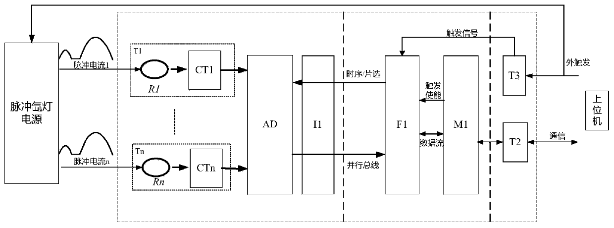
[0048] A pulse discharge current recording device with trigger enable, used for collecting pulse current of pulse xenon lamp power supply and fault judgment, such as figure 1 As shown, the device includes several synchronous acquisition modules T1-Tn, a data processing module, and a trigger communication module that are electrically connected in sequence.
[0049] The synchronous acquisition module T1-Tn is used to acquire the pulse current of the pulsed xenon lamp power supply, and the synchronous acquisition module is composed of Rogowski coils R1-Rn, current sensors CT1-CTn, n-channel analog-to-digital conversion chip AD and digital isolation chip I1 . Taking the first synchronous acquisition module T1 as an example, in this module, the Rogowski coil R1 is connected to the current sensor CT1, the n-way analog-to-digital conversion chip, and the digital isolation chip I1 in sequence, and the Rogowski coil R1 is also connected to the pulse xenon lamp power supply at the same ...
Embodiment 2
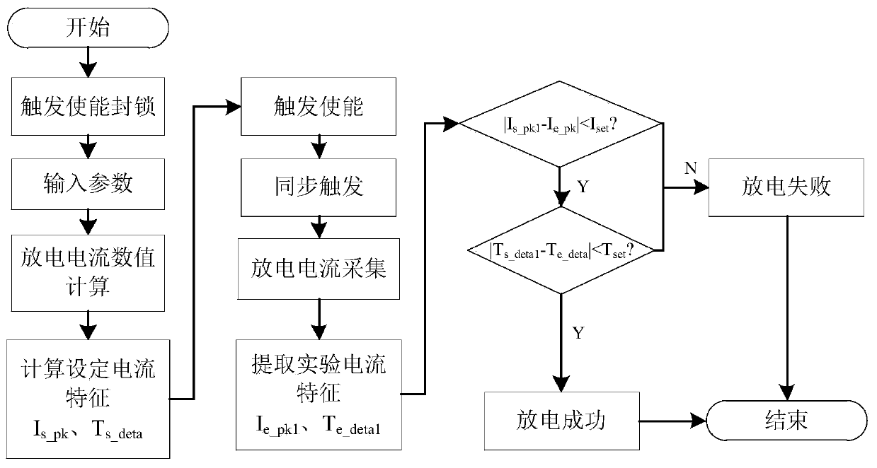
[0058] This embodiment provides a fault identification method based on a pulse discharge current wave recording device. In this embodiment, the fault identification method is based on the pulse discharge current wave recording device with trigger enable in any of the foregoing embodiments. like figure 2 As shown, the method includes:
[0059] S01, the initialization device, after power-on, the upper computer sends the trigger blockade signal P1 to the FPGA unit F1 through the communication circuit T2 and the main control circuit M1, and the FPGA unit F1 detects the trigger blockade signal P1 and turns off the trigger enable;
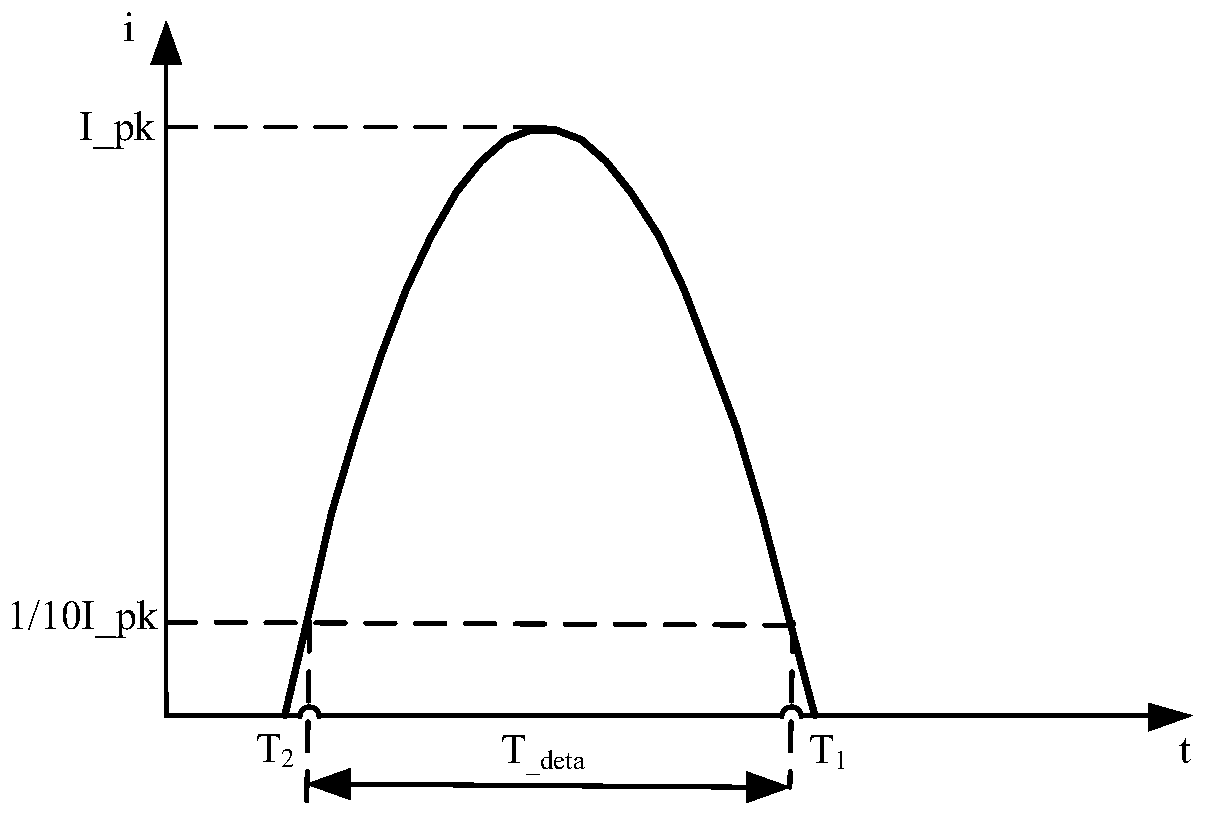
[0060] S02, the host computer sends the current experimental parameter set to the data processing module, and the data processing module calculates and determines the corresponding discharge current waveform characteristics according to the current experimental parameter set;
[0061] In one embodiment, the current experimental parameter set includes p...
PUM
 Abstract
Description
Claims
Application Information
 - R&D
- Intellectual Property
- Life Sciences
- Materials
- Tech Scout
- Unparalleled Data Quality
- Higher Quality Content
- 60% Fewer Hallucinations
Browse by: Latest US Patents, China's latest patents, Technical Efficacy Thesaurus, Application Domain, Technology Topic, Popular Technical Reports.
© 2025 PatSnap. All rights reserved.Legal|Privacy policy|Modern Slavery Act Transparency Statement|Sitemap|About US| Contact US: help@patsnap.com


