A pulse discharge current recording device with trigger enable and fault identification method

A wave recording device and pulse discharge technology, applied in lighting devices, electric light sources, electrical components, etc., can solve the problems of false triggering, poor portability, and low recognition efficiency, and achieve the effect of avoiding the risk of false triggering and improving efficiency.

Active Publication Date: 2022-03-08
LASER FUSION RES CENT CHINA ACAD OF ENG PHYSICS
View PDF16 Cites 0 Cited by
  • Summary
  • Abstract
  • Description
  • Claims
  • Application Information

AI Technical Summary

Problems solved by technology

The above-mentioned device and fault identification method have the following disadvantages: First, there is a risk of false triggering of the non-discharge process due to electromagnetic interference when the device is directly triggered by a synchronous signal; second, the method of manually interpreting the discharge current data has identification efficiency The third is that the method of storing normal discharge data in advance has the disadvantage of poor portability

Method used


Image

  • A pulse discharge current recording device with trigger enable and fault identification method
  • A pulse discharge current recording device with trigger enable and fault identification method
  • A pulse discharge current recording device with trigger enable and fault identification method

Examples


Embodiment 1

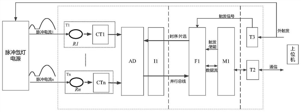
[0048] A pulse discharge current recording device with trigger enable, used for collecting pulse current of pulse xenon lamp power supply and fault judgment, such as figure 1 As shown, the device includes several synchronous acquisition modules T1-Tn, a data processing module, and a trigger communication module that are electrically connected in sequence.

[0049] The synchronous acquisition module T1-Tn is used to acquire the pulse current of the pulsed xenon lamp power supply, and the synchronous acquisition module is composed of Rogowski coils R1-Rn, current sensors CT1-CTn, n-channel analog-to-digital conversion chip AD and digital isolation chip I1 . Taking the first synchronous acquisition module T1 as an example, in this module, the Rogowski coil R1 is connected to the current sensor CT1, the n-way analog-to-digital conversion chip, and the digital isolation chip I1 in sequence, and the Rogowski coil R1 is also connected to the pulse xenon lamp power supply at the same ...

Embodiment 2

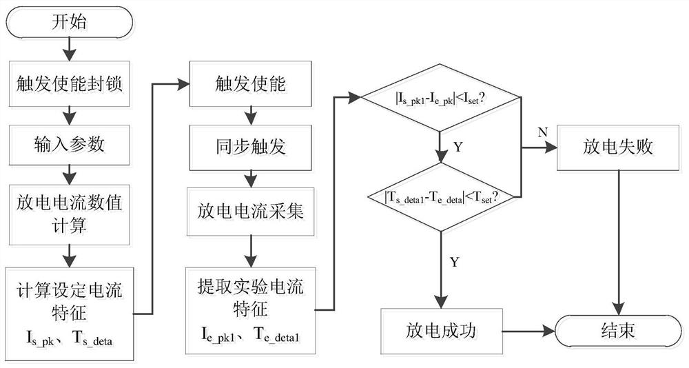
[0058] This embodiment provides a fault identification method based on a pulse discharge current wave recording device. In this embodiment, the fault identification method is based on the pulse discharge current wave recording device with trigger enable in any of the foregoing embodiments. Such as figure 2 As shown, the method includes:

[0059] S01, the initialization device, after power-on, the upper computer sends the trigger blockade signal P1 to the FPGA unit F1 through the communication circuit T2 and the main control circuit M1, and the FPGA unit F1 detects the trigger blockade signal P1 and turns off the trigger enable;

[0060] S02, the host computer sends the current experimental parameter set to the data processing module, and the data processing module calculates and determines the corresponding discharge current waveform characteristics according to the current experimental parameter set;

[0061] In one embodiment, the current experimental parameter set include...


PUM


Abstract

The invention discloses a discharge current wave recording device with trigger enable and a fault identification method, which are used for collecting pulse current of a pulse xenon lamp power supply and fault judgment, and relate to the technical field of pulse power. The device includes an n-channel synchronous acquisition module, a data processing module and a trigger communication module. First, before the discharge of the pulse xenon lamp power supply, the trigger enable signal and experimental parameters are sent to the data processing module through the communication module to calculate the set current characteristics, and the trigger enable signal is released; then, the external trigger signal is sent to the pulse xenon lamp power supply to start Discharge, at the same time, the external trigger signal triggers the communication module to start data collection; finally, the data processing module performs fault judgment on the collected discharge data according to the set current characteristics, and sends the result to the host computer. The invention can avoid the risk of false triggering caused by electromagnetic interference, realizes automatic interpretation of the discharge current based on the discharge current calculation and feature extraction of the nonlinear characteristics of the xenon lamp, and can greatly improve the efficiency of discharge current fault identification.

Description

technical field [0001] The invention relates to the technical field of pulse power, in particular to a discharge current recording device with trigger enable and a fault identification method, which can be applied to the collection of multi-circuit discharge currents of pulse xenon lamp power supplies and the identification of each discharge current fault. Background technique [0002] The pulsed xenon lamp is a device that converts electrical energy into radiant energy in the form of pulse discharge. The energy stored in the capacitor can be released in the form of gas discharge through the xenon lamp tube in a very short time, and a high-temperature plasma is established in the lamp at the same time. , and produce high-brightness radiation. Because of its strong load capacity, good laser beam quality and high pump efficiency, it is often widely used as a pump source for solid-state lasers. [0003] The xenon lamp load of the pulsed xenon lamp power supply is in the form o...

Claims


Application Information

Patent Timeline
Patent Type & Authority Patents(China)
IPC IPC(8): G01R19/25G01R31/44H05B41/36
CPCG01R19/25G01R31/44H05B41/36
Inventor 沈昊苏东陈德怀张雄军赖贵友唐海波郑奎兴陈波彭志涛
Owner LASER FUSION RES CENT CHINA ACAD OF ENG PHYSICS
Why Eureka
Try Eureka