Inspection well lid state monitoring system and working mechanism thereof

A state monitoring and manhole cover technology, which is applied in the general control system, control/regulation system, program control, etc., can solve the problems of limited use conditions, high power consumption of active ranging, and damage of contact points, so as to reduce the frequency of use and improve the quality of life. Environmental adaptability and the effect of improving accuracy

Pending Publication Date: 2020-05-19
王伟新
View PDF8 Cites 2 Cited by
  • Summary
  • Abstract
  • Description
  • Claims
  • Application Information

AI Technical Summary

Problems solved by technology

In the actual implementation process, these methods are limited by the conditions of use, and all have deficiencies.
For example, when using method (1) or method (2), since the sensor is installed on the inspection well cover, when the personnel opens the inspection well by dragging the inspection well cover, the sensor is easy to be damaged; when using method (3) or method (4 ), the person dragging the inspection well cover sideways will also cause damage to the contact point, which will affect the continuous normal operation of the equipment; when the method (4) is used, the signal emission direction of the ranging module is perpendicular to the measured inspection well cover to obtain the most accurate , stable distance output, but the ranging module is installed on the well wall of the inspection well, affected by the construction of the inspection well and the blockage of the well circle, it is not easy to ensure the vertical relationship between the two, and the power supply capacity of the monitoring equipment in the well is limited and the active measurement Due to the large impact of distance power consumption, short-period and long-term ranging cannot be performed

Method used


Image

  • Inspection well lid state monitoring system and working mechanism thereof
  • Inspection well lid state monitoring system and working mechanism thereof

Examples


Embodiment Construction

[0017] The following will clearly and completely describe the technical solutions in the embodiments of the present invention with reference to the accompanying drawings in the embodiments of the present invention. Obviously, the described embodiments are only some, not all, embodiments of the present invention. Based on the embodiments of the present invention, all other embodiments obtained by persons of ordinary skill in the art without creative efforts fall within the protection scope of the present invention.

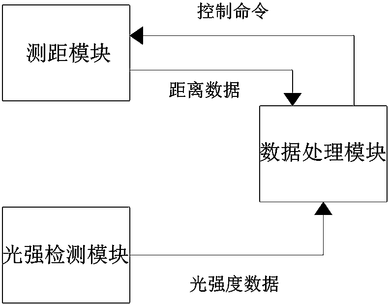
[0018] A inspection well cover state monitoring system, combined with figure 1 As shown, it includes the manhole cover state monitoring equipment installed on the well wall of the inspection well, and the manhole cover state monitoring equipment includes a distance measuring module, a light intensity detection module and a data processing module, and the data processing module is connected with the distance measuring module and the The light intensity detection mod...


PUM


Abstract

The invention provides an inspection well lid state monitoring system. The system comprises a well lid state monitoring device, the well lid state monitoring device comprises a distance measuring module, a light intensity detection module and a data processing module. The data processing module is connected with the distance measuring module and the light intensity detection module. The distance measuring module is used for measuring the distance between the distance measuring module and an inspection well lid and sending measured distance data to the data processing module. The distance measurement module is used for receiving and executing a control command sent by the data processing module, the light detection module is used for monitoring the light intensity at the light detection module and sending the monitored light intensity data to the data processing module, and the data processing module is used for processing the distance data and the light intensity data. The detection result is high in accuracy, and the use frequency of the distance measuring module is reduced, so that the power consumption of well lid state monitoring equipment is reduced.

Description

technical field [0001] The invention relates to the technical field of inspection well monitoring, in particular to a state monitoring system and working mechanism of an inspection well cover. Background technique [0002] The inspection shaft is a well-shaped building set up in underground pipeline engineering, which plays a role in facilitating the inspection, maintenance and dredging of underground pipelines. With economic development and urban expansion, the number of inspection wells has increased dramatically. When the inspection shaft provides convenience for the maintenance of various municipal pipelines, it also brings some safety problems, such as, the disorderly opening or damage of the inspection shaft cover affects the traffic safety of pedestrians and vehicles. Based on this, how to ensure real-time measurable status of the manhole cover switch is a problem that the affiliated enterprises and departments must face. [0003] At present, the methods for detecti...

Claims


Application Information

Patent Timeline
Patent Type & Authority Applications(China)
IPC IPC(8): G05B19/042G01S15/08G01J1/42
CPCG05B19/0425G01S15/08G01J1/4204
Inventor 不公告发明人
Owner 王伟新
Why Eureka
Try Eureka