Dipole antenna with single zero point compensation

A dipole antenna, zero compensation technology, applied in the direction of antenna, resonant antenna, antenna array, etc., to slow down the change of input impedance with frequency, simple structure, and improve impedance bandwidth

Inactive Publication Date: 2020-05-19
XI AN JIAOTONG UNIV +2
View PDF2 Cites 0 Cited by
  • Summary
  • Abstract
  • Description
  • Claims
  • Application Information

AI Technical Summary

Problems solved by technology

However, the radiation characteristic of the traditional dipole antenna is omnidirectional radiation on the H plane, and there

Method used


Image

  • Dipole antenna with single zero point compensation
  • Dipole antenna with single zero point compensation
  • Dipole antenna with single zero point compensation

Examples


Embodiment

[0042] This embodiment includes the following parts

[0043] first part:

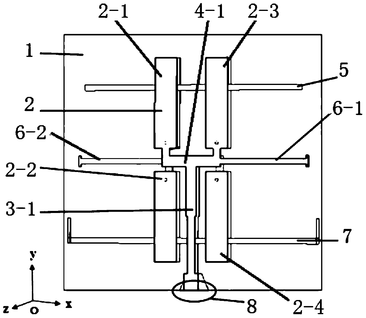
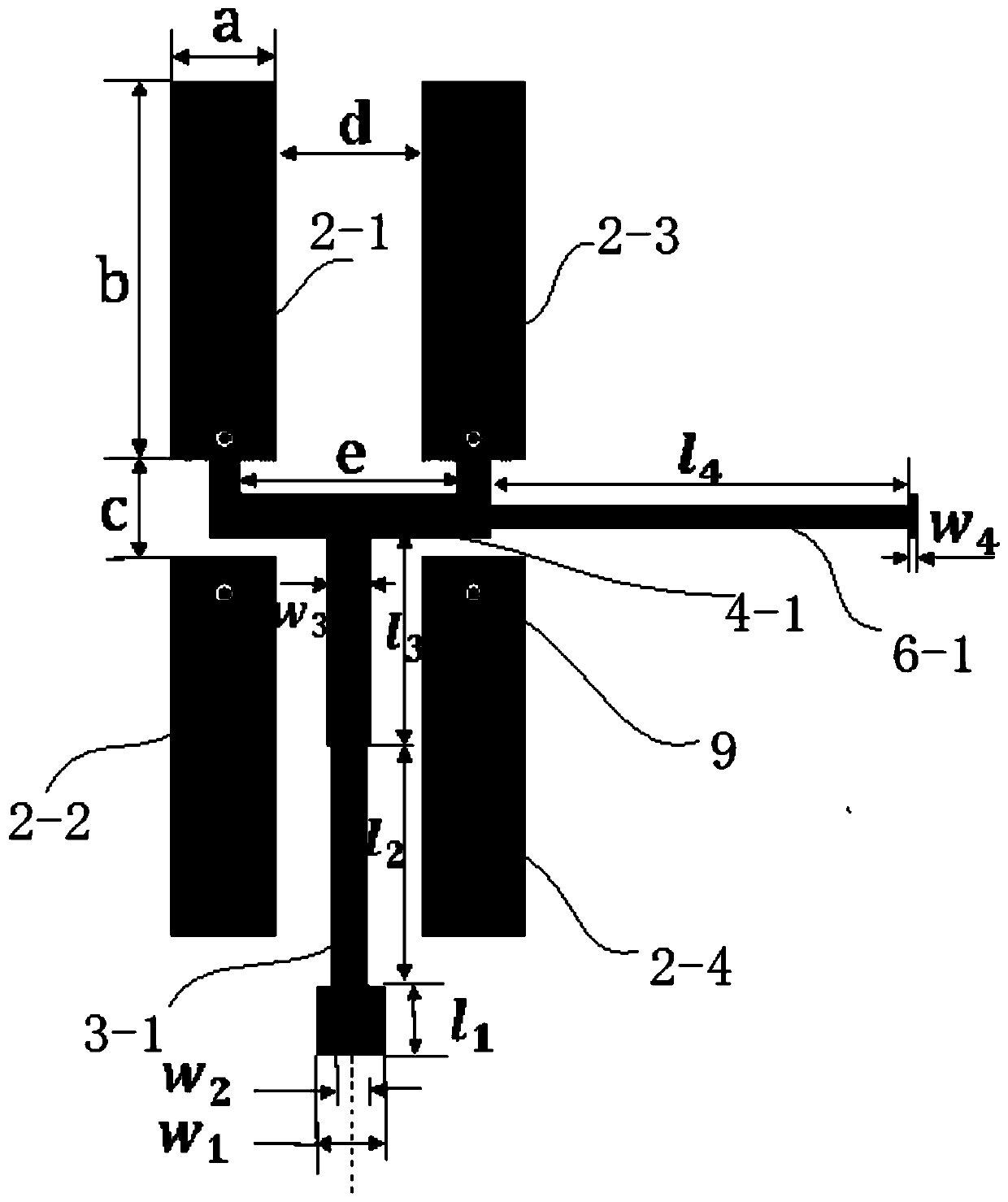
[0044] Such as Figure 1-Figure 4 As shown, the dipole antenna with single zero point compensation in this embodiment is a dipole antenna with single zero point compensation working at 2.4 GHz, the antenna uses parallel double wires as the feeder, and the radiation unit includes a printed dipole antenna And the microstrip Yagi antenna, the entire single null compensated dipole antenna has a 3-layer structure.

[0045] The eight dipole arms of the printed dipole antenna are printed on both sides on the front and back of the dielectric substrate 1, the first dipole arm 2-1, the second dipole arm 2-2, the third dipole arm The sub-arm 2-3 and the fourth dipole arm 2-4 are printed on the front side of the dielectric substrate 1, the fifth dipole arm 2-5, the sixth dipole arm 2-6, and the seventh dipole arm 2-7 and the eighth dipole arm 2-8 are printed on the back side of the dielectric substrate 1, the fi...


PUM


Abstract

The invention discloses a dipole antenna with single zero point compensation. The dipole antenna comprises a dielectric substrate, and a dipole antenna and a microstrip yagi antenna which are arrangedon the dielectric substrate. According to the dipole antenna, dipole arms are arranged on the front surface and the back surface of the dielectric substrate; the dipole arms on the front surface andthe back surface of the dielectric substrate are connected; the dipole arm on the front surface of the dielectric substrate and the dipole arm on the back surface of the dielectric substrate adopt a double-array symmetrical structure; the dipole antenna can perform omnidirectional radiation on an H surface, and a feed port is led out of the dipole antenna; and the microstrip yagi antenna is used for compensating a radiation zero point of the E surface of the dipole antenna in a strong directivity manner in the direction of a director of the microstrip yagi antenna. The dipole antenna with single zero point compensation can achieve the purposes that the antenna is suspended above the space, and the radiation range covers the periphery and the lower portion of the whole space.

Description

technical field [0001] The invention belongs to the technical field of antennas, in particular to a dipole antenna with single zero point compensation. Background technique [0002] Omnidirectional antennas have been widely used in the field of mobile communications. With the rapid development of electronic technology and communication industry, the requirements for omnidirectional antennas are getting higher and higher. As an omnidirectional radiation antenna, printed dipole antennas have become an antenna An important research direction of the subject. In recent years, top-mounted omnidirectional radiation antennas have been widely used in indoor distributed antenna systems, but traditional top-mounted omnidirectional radiation antennas usually use monopole antennas, and top-mounted omnidirectional radiation antennas based on dipole antennas are not Not studied in depth. Compared with monopole antennas, dipole antennas do not need to be installed on a larger ground plane...

Claims


Application Information

Patent Timeline
IPC IPC(8): H01Q1/38H01Q1/50H01Q9/06H01Q9/16H01Q15/14H01Q19/30H01Q21/00
CPCH01Q1/38H01Q1/50H01Q9/16H01Q9/065H01Q15/14H01Q19/30H01Q21/00
Inventor 陈娟鲁艺禹旭敏
Owner XI AN JIAOTONG UNIV
Why Eureka
Try Eureka