Rapid cooling type injection molding device

A cooling and fast technology, applied in the field of injection molding equipment, can solve problems such as poor effect, achieve novel design, strong practicability, and increase the effect of injection molding precision

Inactive Publication Date: 2020-05-22
廖素英
View PDF3 Cites 7 Cited by
  • Summary
  • Abstract
  • Description
  • Claims
  • Application Information

AI Technical Summary

Problems solved by technology

[0004] Chinese patent (notification number: CN209851515U) discloses a rapid cooling injection molding device, including a heating furnace, an electric heating tube, a bottom plate and a concave injection mold. An input pipe and an output pipe are provided, and an input valve and an output valve are respectively provided on the input pipe and the output pipe. and the rotating fan blade, the middle part of the top of the working box is connected with a working groove, the concave injection mold is placed inside the working groove, the bottom of the concave injection mold is in contact with the inner bottom side wall of the working box, and the front, rear and left ends of the concave injection mold and the right end are respectively in contact with the inner front side wall, the inner rear side wall, the inner left side wall and the inner right side wall of the working box. Although this device can realize the rapid cooling of the injection mold to a certain extent, it still has no effect in actual use. Good, therefore, need further improvement

Method used


Image

  • Rapid cooling type injection molding device
  • Rapid cooling type injection molding device
  • Rapid cooling type injection molding device

Examples


Embodiment 1

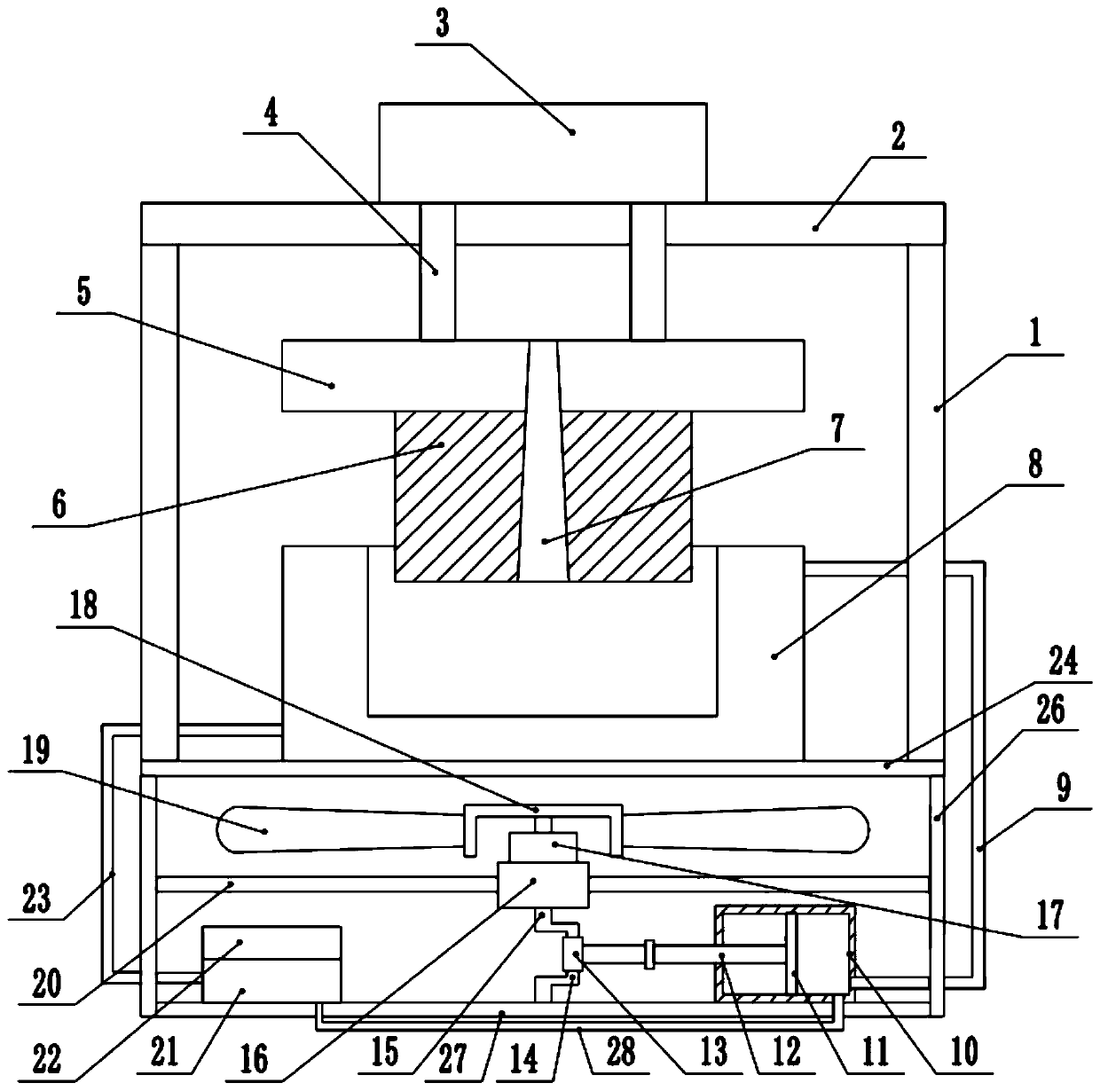
[0029] refer to Figure 1~3 , in an embodiment of the present invention, a rapid cooling injection molding device includes a support frame 1, a top plate 2 is installed on the upper end of the support frame 1, and a power unit 3 is installed on the upper end of the top plate 2, and the power unit 3 is a hydraulic cylinder or an air cylinder. The power shaft 4 is installed at the lower end of the part 3, and the mold seat 5 is installed at the bottom end of the power shaft 4, so that the upper mold 6 can move up and down under the action of the power part 3, and an injection channel is provided between the mold seat 5 and the interior of the upper mold 6 7. To meet the needs of injection molding materials, the upper mold 6 is installed at the lower end of the mold base 5, the support plate 24 is installed at the bottom end of the support frame 1, the lower mold 8 is installed at the middle of the upper end of the support plate 24, and the upper mold 6 and the lower mold 8 are in...

Embodiment 2

[0031] In another embodiment of the present invention, the difference between this embodiment and the above-mentioned embodiment is that a refrigeration mechanism 22 is installed on the upper end of the refrigeration box 21, and the refrigeration mechanism 22 includes a refrigeration plate 221, and the lower end of the refrigeration plate 221 is provided with a The cold end 223, the cold end 223 is located inside the refrigeration box 21, the upper end of the refrigerating sheet 221 is provided with a hot end 222, and the refrigerating sheet 221 is a semiconductor refrigerating sheet, which can realize rapid cooling.

[0032] The present invention, when working, first injects materials into the injection channel 7, and realizes the opening and closing of the upper mold 6 and the lower mold 8 through the power part 3. During this process, the drive motor 17 is started to make the drive shaft 15 rotate. On the one hand, the rotary blade 19 is rotated to realize air cooling and heat...


PUM


Abstract

The invention relates to the technical field of injection molding equipment, and discloses a rapid cooling type injection molding device. The rapid cooling type injection molding device comprises a supporting frame, a top plate is installed at the upper end of the supporting frame, a power piece is installed at the upper end of the top plate, a power shaft is installed at the lower end of the power piece, a mold base is installed at the bottom end of the power shaft, an upper mold is installed at the lower end of the mold base, a supporting plate is installed at bottom end of the supporting frame, a lower mold is installed in middle of upper end of supporting plate, fixing frames are installed on the two sides of the lower end of the supporting plate, a limiting plate is installed betweenthe middles of the fixing frames, a motor base is installed in the middle of the limiting plate, a driving motor is installed at the upper end of the motor base, a driving shaft is installed at the upper end and the lower end of the driving motor, a blade base is installed at the upper end of the driving shaft, rotating blades are installed at two ends of the blade base, the middle of the lower end of driving shaft is provided with a crank, and the middle of the crank is provided with a sliding sleeve. According to the rapid cooling type injection molding device, distribution of refrigeratingfluid among a piston cavity, a refrigerating box and the lower mold is achieved, the refrigerating effect during injection molding is achieved, meanwhile, rapid cooling is further achieved, and the injection molding precision is greatly improved.

Description

technical field [0001] The invention relates to the technical field of injection molding equipment, in particular to a rapid cooling injection molding device. Background technique [0002] The injection molding device is a device used for injection molding of industrial products, which makes it more convenient for the staff to inject industrial products. It has been widely used in the field of injection molding equipment; the existing injection molding devices include heating furnaces , electric heating tube, base plate and concave injection mold, a heating chamber is arranged inside the heating furnace, the top left side and the bottom of the heating furnace are respectively connected with input pipes and output pipes, and input valves are respectively arranged on the input pipes and output pipes And the output valve, the electric heating tube is arranged around the outer wall of the heating furnace, and the bottom of the concave injection mold is in contact with the middle...

Claims


Application Information

Patent Timeline
Patent Type & Authority Applications(China)
IPC IPC(8): B29C45/73
CPCB29C45/73
Inventor 廖素英
Owner 廖素英
Why Eureka
Try Eureka