Locknut and its method of use and component assembly method

A technology for locking nuts and nut bodies, applied in the directions of nuts, threaded fasteners, screws, etc., can solve the problems of easily damaged screw shafts, and achieve the effects of reducing cracking, protecting screw shafts, and convenient processing

Active Publication Date: 2021-11-19
台州市恩晓科技咨询有限公司
View PDF6 Cites 0 Cited by
  • Summary
  • Abstract
  • Description
  • Claims
  • Application Information

AI Technical Summary

Problems solved by technology

It solves the problem that the existing locknut is easy to damage the screw shaft through violent disassembly

Method used


Image

  • Locknut and its method of use and component assembly method
  • Locknut and its method of use and component assembly method
  • Locknut and its method of use and component assembly method

Examples


Embodiment 1

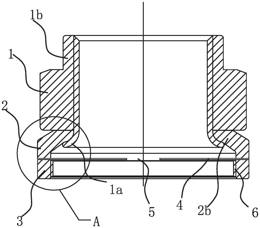
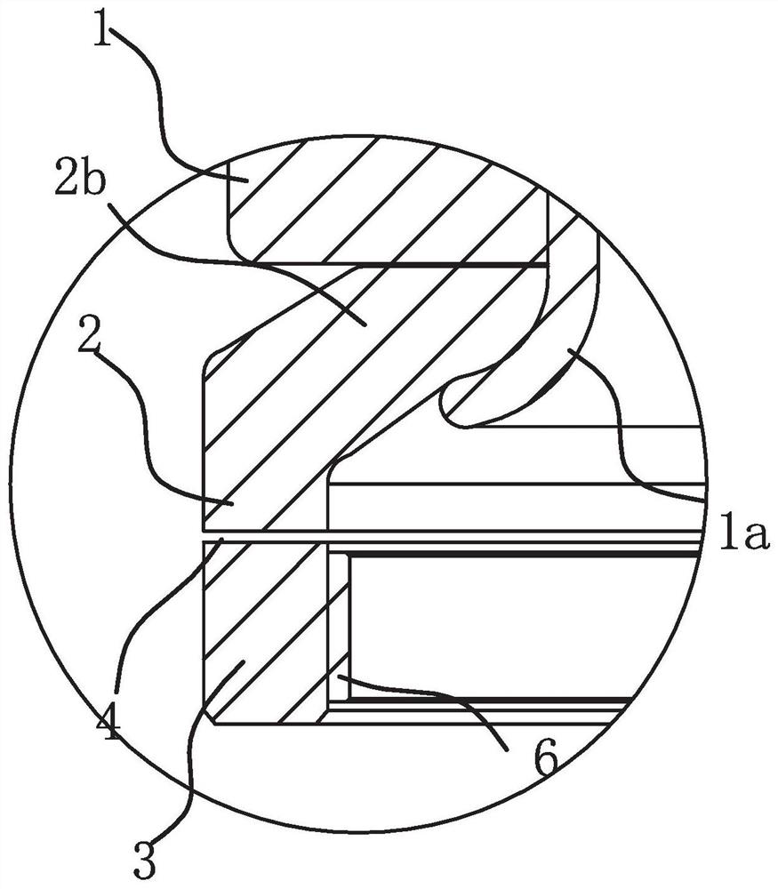
[0066] Such as figure 1 , image 3 , Figure 5 and Figure 8 As shown, the locknut includes a nut body 1 and a washer 2, the washer 2 is movably connected to the nut body 1, and the locknut also includes an open locking ring 3, the screw shaft passes through the locking ring 3, and is locked. The ring 3 is connected with the locknut, and the internal size of the locking ring 3 can be enlarged or reduced after being subjected to an external force. The nut body 1 has an internal thread and is threaded on the screw shaft. Its bottom has a bent stopper 1a. The function of the stopper 1a is to limit the axial movement of the washer 2. The washer 2 can realize circumferential rotation. The nut body After 1 and washer 2 are installed to the preset position of the screw shaft, the locking ring 3 is clamped by the clamping device until the locking ring 3 is firmly attached to the screw shaft, so that the locking ring 3 hugs the screw shaft tightly, thereby Realize the overall anti-...

Embodiment 2

[0075] Such as figure 1 , image 3 , Figure 6 and Figure 8 As shown, the difference between this embodiment and Embodiment 1 is that the locking ring 3 is connected to the washer 2, the top of the washer 2 is the connecting part 2b, the bottom of the washer 2 is connected with the locking ring 3 and a deformation gap is formed between them 4. The washer 2 has an open structure and the opening position is the same as that of the lock ring 3. In this scheme, both the washer 2 and the locking ring 3 are of opening structure, the limiting part 1a on the nut body 1 is formed first, and then the inner diameter of the washer 2 is enlarged through the structure of the opening 2a of the washer so that the connecting part 2b is sleeved in the limit On the position part 1a, it is sufficient to close the mouth at last. This solution does not need stamping and is easy to process.

[0076] The method for assembling the locknut parts in the above scheme includes the following steps:

...

Embodiment 3

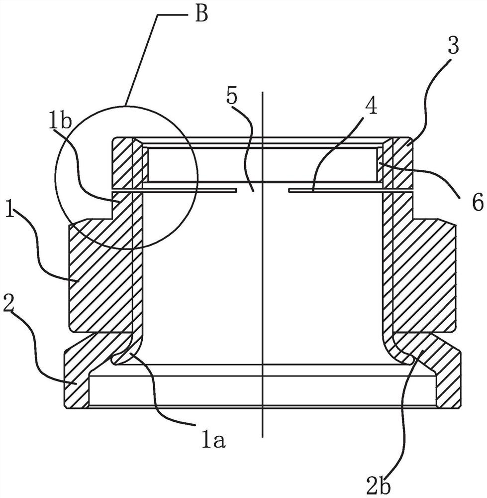
[0081] Such as figure 2 , Figure 4 , Figure 7 and Figure 8 As shown, the difference between this embodiment and Embodiment 1 is that the locking ring 3 is located on the nut body 1, the top of the nut body 1 is extended with an extension 1b, the bottom end of the extension 1b is integrated with the nut body 1, and the extension 1b The top end is connected with the locking ring 3 and a deformation gap 4 is formed between the two. In this solution, also, the extension part 1b and the locking ring 3 are connected through the connecting section 5, and the locking ring 3 can be obtained by processing the extension part 1b. This solution keeps the washer 2 in the traditional structure, improves on the self-contained structure extension part 1b of the traditional locknut, makes full use of the existing structure, and realizes corresponding functions.

[0082] The detailed structures, specific component sizes and principles not mentioned in this application document are all ex...


PUM


Abstract

The invention provides a locknut, a method for using the same and a method for assembling components, which belong to the field of machinery. The locknut includes a nut body and a washer. The washer is movably connected to the nut body. The locknut also includes an open lock ring. The screw shaft passes through the lock ring. The lock ring is connected with the lock nut and locked. The internal size of the ring can be enlarged or reduced after being subjected to external force. The anti-loosening nut is beneficial to the subsequent disassembly and is beneficial to the protection of the screw shaft. The use method of the locknut includes pre-installation, clamping and disassembly steps. By clamping and pulling the locking ring, there is no violent disassembly step, which fully protects the screw shaft. The component assembly method includes the steps of flaring sleeve and shrinking closing, and has novel design, high yield rate and convenient processing.

Description

technical field [0001] The invention belongs to the field of machinery, and relates to a locknut, a method for using the same, and a method for assembling components. Background technique [0002] Lock nuts are widely used in the field of automotive fastening and mechanical fastening. is common. [0003] For example, the application number is 2018201266082, the application date is 2018.1.25, and the name is a utility model patent for a locknut and threaded connection, which records a locknut, including a nut body, the nut body is connected to a bolt through a thread, and the bolt's The threaded section is provided with grooves along the axial direction, and an extension section is provided at the end of the nut body. The extension section is a hollow cylindrical structure, the nut body and the extension section are coaxial, and the inner diameter of the extension section is larger than the thread diameter of the nut body. The above-mentioned structure provides a locknut an...

Claims


Application Information

Patent Timeline
Patent Type & Authority Patents(China)
IPC IPC(8): F16B39/26
CPCF16B39/26
Inventor 林玉华林绍连林思杨
Owner 台州市恩晓科技咨询有限公司
Why Eureka
Try Eureka