
Device for monitoring real-time running state of equipment by utilizing USB interface and working method thereof

A technology of USB interface and monitoring equipment, which is applied in the field of devices that use USB interface to monitor the real-time running status of equipment, can solve the problems of no built-in, inconvenient product testing, etc., and achieve the effect of improving convenience and improving the efficiency of development and debugging

Pending Publication Date: 2020-05-22
YANGO UNIV
View PDF0 Cites 0 Cited by
  • Summary
  • Abstract
  • Description
  • Claims
  • Application Information

AI Technical Summary

Problems solved by technology

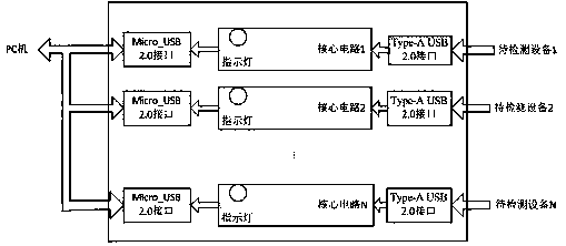
[0004] In view of this, in order to solve the problem that the existing electronic equipment is not convenient for product testing because there is no built-in indicator light, display screen and serial port before leaving the factory, the present invention provides a device and its working method for monitoring the real-time running status of the equipment using a USB interface. No need to add additional debugging interface, which improves the convenience of electronic equipment testing

Method used


Image

  • Device for monitoring real-time running state of equipment by utilizing USB interface and working method thereof
  • Device for monitoring real-time running state of equipment by utilizing USB interface and working method thereof
  • Device for monitoring real-time running state of equipment by utilizing USB interface and working method thereof

Examples


Embodiment Construction

[0021] The present invention will be further described below in conjunction with the accompanying drawings and embodiments.

[0022] It should be pointed out that the following detailed description is exemplary and intended to provide further explanation to the present application. Unless defined otherwise, all technical and scientific terms used herein have the same meaning as commonly understood by one of ordinary skill in the art to which this application belongs.

[0023] It should be noted that the terminology used here is only for describing specific implementations, and is not intended to limit the exemplary implementations according to the present application. As used herein, unless the context clearly dictates otherwise, the singular is intended to include the plural, and it should also be understood that when the terms "comprising" and / or "comprising" are used in this specification, they mean There are features, steps, operations, means, components and / or combinations...


PUM


Abstract

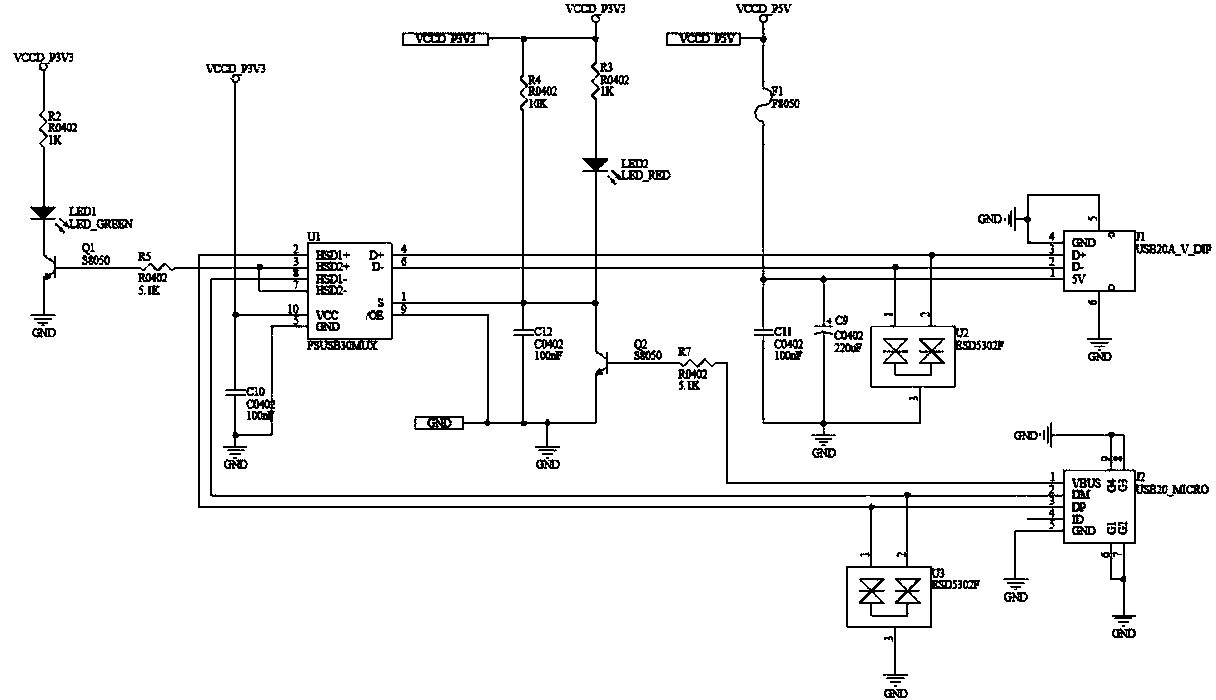
The invention relates to a device for monitoring the real-time running state of equipment by utilizing a USB interface and a working method of the device. The device comprises N groups of USB monitoring circuits; each group of USB monitoring circuits are connected in parallel; each group of USB monitoring circuits comprises a core circuit, and a Type-A USB 2.0 interface and a Micro _ USB 2.0 interface which are connected with the core circuit; the Type-A USB 2.0 interface is also connected with a device to be detected; the Micro _ USB 2.0 interface is also connected with an external PC (Personal Computer); and the core circuit comprises a USB 2.0 Switch chip and an indicating lamp display circuit. The USB 2.0 Switch chip is connected with the device to be detected through the Type-A USB 2.0 interface to detect the D + / D- pin level state of the USB 2.0 Switch chip, and when the device to be detected detects that D + / D- is high, the device to be detected enters a test mode; the USB 2.0 Switch chip is connected with the indicating lamp display circuit to display different test states of the device to be detected. And the USB 2.0 Switch chip is connected with the PC through the Micro _USB 2.0 interface to print a log of the device to be detected through the PC. According to the invention, an additional debugging interface is not required to be added, and the electronic equipment testing convenience is improved.

Description

technical field [0001] The invention relates to the technical field of power electronics detection, in particular to a device and a working method for monitoring the real-time running state of equipment using a USB interface. Background technique [0002] In the process of developing an electronic product, developers often need to perform long-term stress tests on the electronic product, such as placing it in an incubator for high and low temperature tests, to verify the stability of the device for a long time. It can be seen that real-time monitoring and abnormal diagnosis of equipment status are the key guarantees for the stable operation of inspection equipment. Existing monitoring technical solutions generally use the built-in indicator light or display screen on the device to visually observe the test results, or connect to the PC terminal / host computer through the serial port of the device, print out debugging information and input debugging commands, and then analyze ...

Claims


Application Information

Patent Timeline
Patent Type & Authority Applications(China)
IPC IPC(8): G06F11/22G06F11/32
CPCG06F11/2268G06F11/325
Inventor 林虹吴良峰
Owner YANGO UNIV
Learn More