Driving method of electronic ink for display

A technology of electronic ink and driving method, applied in static indicators, instruments, etc., can solve the problems of instability, reduction of electrowetting aperture ratio, influence of display effect, etc., to improve the degree of shrinkage, realize aperture ratio, and overcome easy dispersion. Effect

Pending Publication Date: 2020-05-22
UNIV OF ELECTRONICS SCI & TECH OF CHINA ZHONGSHAN INST
View PDF7 Cites 0 Cited by
  • Summary
  • Abstract
  • Description
  • Claims
  • Application Information

AI Technical Summary

Problems solved by technology

[0002] Electrowetting (EWD) display technology belongs to a reflective display technology. When an electrowetting device is not applied with an electric field, the dyed polar liquid inside the device covers the entire pixel unit, and the pixel unit displays the color of the polar liquid. , when the driving voltage is applied, the dyed liquid (such as ink) of the pixel unit shrinks, thereby exposing the white base plate, and the dyed liquid of the pixel unit switches between the state of tiling or shrinking, so as to realize the grayscale display of the pixel. However, the existing driving voltage Most of the waveforms use square waves or driving waveforms with different slopes. There are problems such as low aperture ratio of electrowetting display and inconsistent and unstable changes in the rising and falling curves of the aperture ratio.
[0003] like figure 1 The square wave voltage shown, it meets the needs of fast response of electrowetting, but ink dispersion phenomenon will appear in driving pixels of electrowetting display, the ink droplet usually shrinks to two or three corners, the ink and The increase in the contact area of ​​the substrate reduces the opening ratio of electrowetting, which affects the display effect. The more ink droplets are dispersed, the lower the opening ratio is, and the smaller the display area of ​​the white substrate is, the shape of the ink greatly affects the display effect. Electrowetting reveals the area of ​​a white substrate
[0004] like figure 2 The ladder waveform voltage shown, although it greatly reduces the problem of droplet dispersion, and the shrinkage of the waveform becomes stable and reliable, but the opening ratio of electrowetting is not ideal, and it is difficult to meet the effect of electrowetting dynamic display

Method used


Image

  • Driving method of electronic ink for display
  • Driving method of electronic ink for display
  • Driving method of electronic ink for display

Examples


Embodiment Construction

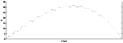
[0023] refer to image 3 , a driving method of electronic ink for display, including calculating the electrowetting ink driving voltage U of the electrowetting original, after editing the driving voltage U of the electrowetting ink with an editable function generator, the voltage is obtained through a high-voltage amplifier Wetting the ink driving voltage waveform, loading the electrowetting ink driving voltage waveform output by the high voltage amplifier to the input port of the electrowetting display.

[0024] The driving voltage U of the electrowetting ink is:

[0025] U=10 -4 x 2 +1(sin(x)+bx).

[0026] Where b is an arbitrary constant, and generally b takes 0 or 1.

[0027] The calculation and loading of the electrowetting ink drive U is an existing technology, and a computer with readable memory can be used to perform the calculation, and a common voltage loader can be used to load the output voltage of the high-voltage amplifier.

[0028] The driving voltage U of ...


PUM


Abstract

The invention discloses a driving method of electronic ink for display. The method comprises the steps of calculating the electrowetting ink driving voltage U of an electrowetting original, editing the electrowetting ink driving voltage U, and forming and loading a voltage waveform. Due to waveform characteristics of sine waves, the shrinkage stability of the electrowetting ink is improved. The maximum shrinkage degree of the electrowetting ink is effectively improved. The problems that ink droplets are easy to disperse and the shrinkage degree of the ink is low in the prior art are solved. The aperture opening ratio can be more accurately controlled. The movement shape of the ink is more effectively controlled, and the stability of the ink is improved. The maximization of the aperture opening ratio is realized.

Description

technical field [0001] The invention relates to the technical field of electrowetting display, in particular to a driving method of electronic ink for display. Background technique [0002] Electrowetting (EWD) display technology belongs to a reflective display technology. When an electrowetting device is not applied with an electric field, the dyed polar liquid inside the device covers the entire pixel unit, and the pixel unit displays the color of the polar liquid. , when the driving voltage is applied, the dyed liquid (such as ink) of the pixel unit shrinks, thereby exposing the white base plate, and the dyed liquid of the pixel unit switches between the state of tiling or shrinking, so as to realize the grayscale display of the pixel. However, the existing driving voltage Most of the waveforms use square waves or driving waveforms with different slopes, and there are problems such as low aperture ratio displayed by electrowetting, and inconsistent and unstable changes in...

Claims


Application Information

Patent Timeline
IPC IPC(8): G09G3/34
CPCG09G3/348
Inventor 易子川吴卓宇迟锋刘黎明杨健君张智张崇富水玲玲
Owner UNIV OF ELECTRONICS SCI & TECH OF CHINA ZHONGSHAN INST
Why Eureka
Try Eureka