Energy dissipation structure for water conveying hole

A technology for water conveyance and energy dissipation, which is applied in water conservancy projects, marine engineering, instruments, etc., can solve the problems of disrepair, long service life, and broken embankments, and achieves the effect of real-time monitoring reliability.

Active Publication Date: 2020-05-26
河南华北水利水电勘察设计有限公司
View PDF6 Cites 0 Cited by
  • Summary
  • Abstract
  • Description
  • Claims
  • Application Information

AI Technical Summary

Problems solved by technology

[0005] The disadvantage of the above-mentioned prior art is that the energy-dissipating structure of the water delivery tunnel generally has a relatively long service life, and because the reservoir also lacks a special person to manage each part, the water delivery tunnel often falls into disrepair for a long time, and once The energy dissipation effect of the water tunnel is not good, and the impact of the water flow on the downstream dam is very large, which may even lead to the collapse of the embankment

Method used


Image

  • Energy dissipation structure for water conveying hole
  • Energy dissipation structure for water conveying hole
  • Energy dissipation structure for water conveying hole

Examples


Embodiment Construction

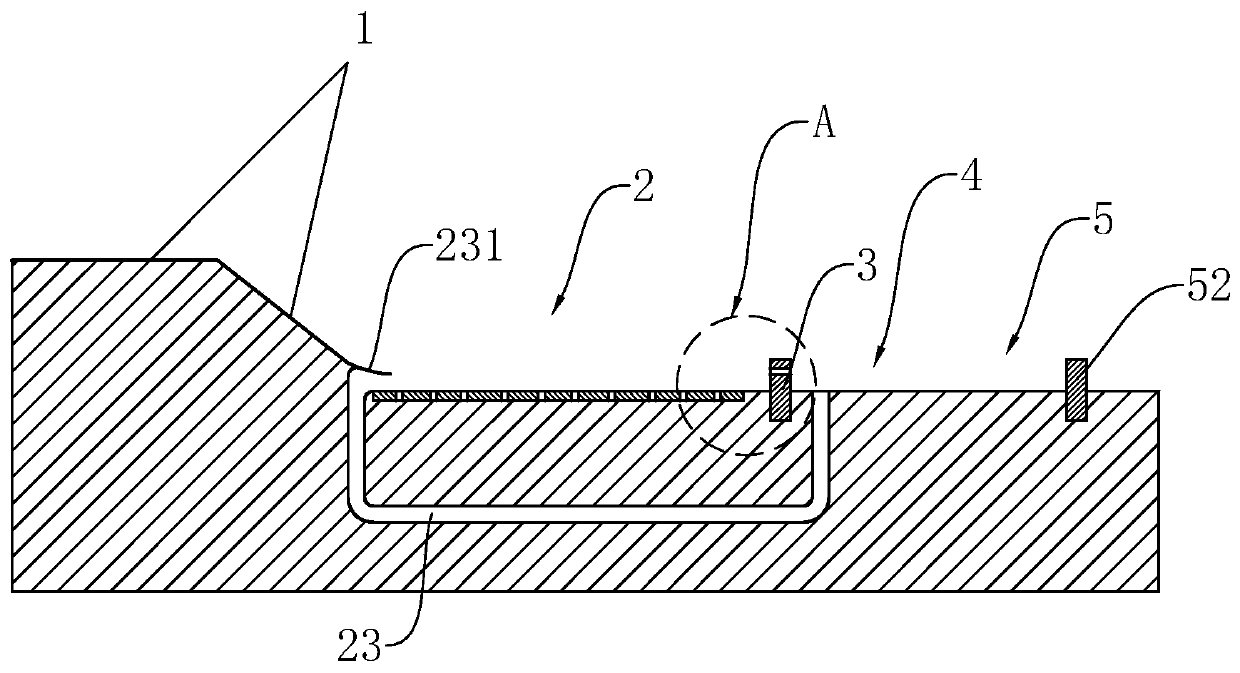
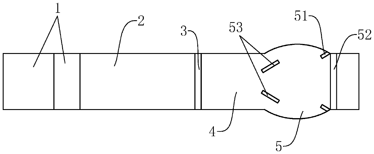
[0032] Such as figure 1 As shown, this embodiment introduces an energy dissipation structure of a water delivery tunnel, including an apron 1, a stilling basin 2, a stilling sill 3, a buffer section 4 and a second stilling basin 5 arranged sequentially from upstream to downstream, The apron 1 is located upstream of the stilling basin 2, the stilling sill 3 is located at the end of the stilling basin 2, the stilling sill 3 protrudes vertically from the bottom of the stilling basin 2, and the water first flows through the apron 1 and enters the stilling basin 2, under the blocking action of the stilling sill 3, the water flow forms a hydraulic jump upstream of the stilling sill 3, eliminating most of the water flow energy, and then enters the buffer section 4 and the second stilling pool 5, using the second stilling pool The force pool 5 performs energy dissipation for the second time, so that the water flow can flow out smoothly and slowly.

[0033] Such as figure 1 As shown,...


PUM


Abstract

The invention relates to the technical field of water conveyance projects, in particular to an energy dissipation structure for a water conveying hole. The energy dissipation structure for the water conveying hole comprises a protection apron, a stilling pool and a baffle sill; the protection apron is positioned upstream the stilling pool; the baffle sill is positioned at the tail end of the stilling pool; the stilling pool is vertically protruded from the bottom of the stilling pool; a horizontal flow measurement pipeline is buried in the baffle sill; the flow measurement pipeline communicates with the space in two sides of the baffle sill; and a flowmeter is arranged on the flow measurement pipeline in a communicating manner. According to the energy dissipation structure for the water conveying hole, the water pressure upstream the baffle sill is high, and the water pressure downstream the baffle sill is relatively low, so that water flow upstream the baffle sill can flow from the flow measurement pipeline into the downstream of the baffle sill, and the flow rate of the water flow flowing from the flow measurement pipeline can be measured by utilizing the flowmeter so that the pressure difference between the water pressure on the two sides of the baffle sill is deduced, thereby judging whether a force dissipating effect is reduced because of the erosion of the baffle sill caused by long time use; and therefore, the effect of remotely monitoring the reliability of the energy dissipation structure for the water conveying hole is achieved, which facilitates the overall management of water conservancy facilities of various places for a water conservancy bureau and facilitates check and repair.

Description

technical field [0001] The invention relates to the technical field of water delivery engineering, in particular to an energy dissipation structure of a water delivery tunnel. Background technique [0002] Reservoirs are usually composed of three parts: water retaining buildings, water discharge buildings and water delivery buildings, which become the "three major parts" of the reservoir. The function of the water delivery buildings is to transport water from the reservoir to the downstream for irrigation and power generation. and water supply needs, the water delivery tunnel is the first structure through which the reservoir delivers water to the outside. [0003] Where it is used for irrigation and water supply, the water flow out of the water tunnel must have high stability, and the flow rate and water level of the water flow must be relatively stable. Therefore, the water flow upstream of the water tunnel must be eliminated in the water tunnel. can handle. The energy d...

Claims


Application Information

Patent Timeline
Patent Type & Authority Applications(China)
IPC IPC(8): E02B8/06G01N19/08G01L13/00
CPCE02B8/06G01L13/00G01N19/08
Inventor 王英杰张龙飞吴卿刘玉忠卢宏伟宋永嘉王安东其他发明人请求不公开姓名
Owner 河南华北水利水电勘察设计有限公司
Why Eureka
Try Eureka