Static load experiment test system based on distributed optical fiber sensor pile foundations

A distributed optical fiber, test and test technology, applied in the test of infrastructure, infrastructure engineering, construction, etc., can solve the problems of poor reliability of test data, limited number of tests, difficult construction protection, etc., to achieve accurate removal of temperature effects, Real-time monitoring of reliability effects

Inactive Publication Date: 2019-03-29
ZHEJIANG ZHONGXIN POWER MEASUREMENT & CONTROL TECH
View PDF0 Cites 0 Cited by
  • Summary
  • Abstract
  • Description
  • Claims
  • Application Information

AI Technical Summary

Problems solved by technology

At present, the static load test of pile foundation is mainly monitored by point sensors such as steel stress gauges or concrete strain gauges embedded in different sections of the pile, which has the characteristics of limited number of tests, inconvenient installation, difficult construction protection and easy damage, and poor reliability of test data. , and during the project operation period, the deflection of foundation piles is rarely monitored, so the actual force status of foundation piles is an unknown quantity

Method used


Image

  • Static load experiment test system based on distributed optical fiber sensor pile foundations
  • Static load experiment test system based on distributed optical fiber sensor pile foundations

Examples


Embodiment Construction

[0018] Embodiments of the present invention will be described in detail below in conjunction with the accompanying drawings.

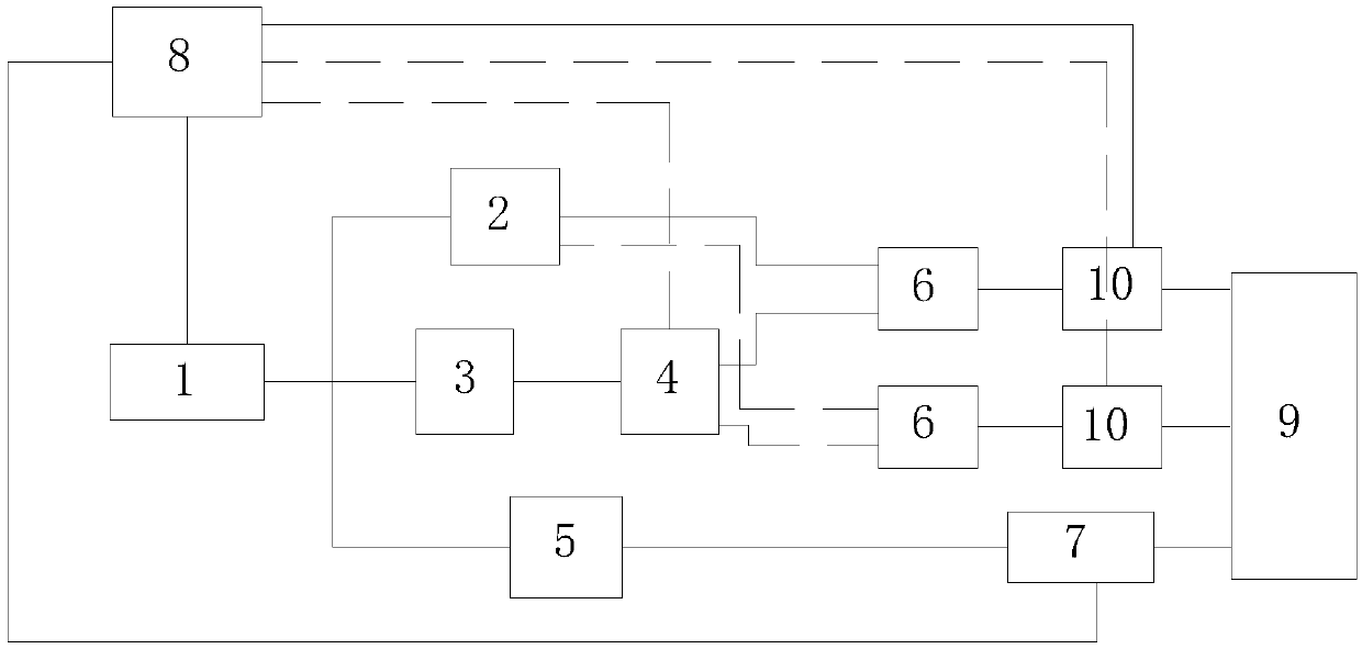
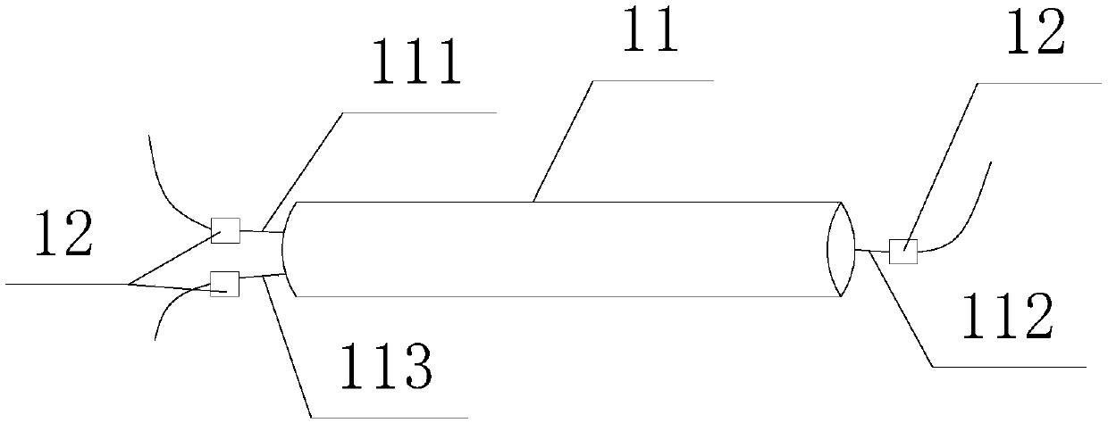
[0019] refer to Figure 1 to Figure 2 , the present invention is based on a distributed optical fiber sensor pile foundation static load test system, including industrial PC1, Brillouin module 2, OTDR module 3 (Optical Time Domain Reflectometer), Raman module 5 and sensing optical cable 11, industrial PC1 The Brillouin module 2, OTDR module 3 and Raman module 5 are respectively connected, and the sensing optical cable 11 and the pile foundation 9 are poured together. The sensing optical cable 11 includes a single-core optical fiber and a multi-mode optical fiber. The exposed part of the mode fiber on the outside of the pile foundation 9 includes a head 111 and a tail 112, and the part of a multimode fiber exposed on the outside of the pile foundation 9 is 113; the Brillouin module 2 and the OTDR module 3 are jointly connected to a single-core single-mo...


PUM


Abstract

The invention provides a static load experiment test system based on distributed optical fiber sensor pile foundations. The system comprises an industrial PC, a Brillouin module, an OTDR module, a Raman module and a sensing optical cable; the industrial PC is connected with the Brillouin module, the OTDR module and the Raman module separately, the sensing optical cable and the pile foundation arepoured together, the sensing optical cable internally comprises a one-core single-mode optical fiber and a one-core multi-mode optical fiber, the Brillouin module and the OTDR module are jointly connected with the one-core single-mode optical fiber, and the Raman module is connected with the one-core multi-mode optical fiber. By means of the static load experiment test system based on the distributed optical fiber sensor pile foundation, the Raman module and the multi-mode optical fiber are adopted for temperature measurement, and the influence of the temperature quantity can be more accurately removed; loss monitoring of the Brillouin measurement optical fiber is achieved by the OTDR module in a static load strain test of the pile foundation, major faults such as fiber breakage can be timely found, the static load test can be timely stopped, and the reliability of pouring optical fibers and sensor connecting optical fibers can be monitored in real time.

Description

technical field [0001] The invention relates to a pile foundation detection system, in particular to a pile foundation static load test system based on distributed optical fiber sensors. Background technique [0002] Pile foundation engineering is an underground concealed engineering with complex construction procedures, high technical requirements, and difficult construction. The quality of the project is often difficult to control, and various quality problems will occur if there is a slight carelessness. Paying attention to the inspection of pile foundation is conducive to the study of the law of interaction between piles and soil and the natural law of pile deformation, which is conducive to providing theoretical guidance and data support for work innovations such as pile type design and construction technology, and is conducive to improving construction quality and ensuring project quality and safety. , which is conducive to the control and saving of engineering costs. ...

Claims


Application Information

Patent Timeline
Patent Type & Authority Applications(China)
IPC IPC(8): E02D33/00
CPCE02D33/00
Inventor 李昊王旭峰张真毅周建华周芳
Owner ZHEJIANG ZHONGXIN POWER MEASUREMENT & CONTROL TECH
Why Eureka
Try Eureka