A Blasting Method for Reducing Harmful Effects Based on Wave Catch-Energy Dissipation

A wave blocking and effect technology, applied in the field of mining construction, can solve the problems of reducing the stability of surrounding rocks and destroying surrounding structures, and achieve the effect of improving protection and stability

Active Publication Date: 2022-05-17
ANHUI UNIV OF SCI & TECH
View PDF0 Cites 0 Cited by
  • Summary
  • Abstract
  • Description
  • Claims
  • Application Information

AI Technical Summary

Problems solved by technology

However, ordinary blasting methods will produce harmful effects such as vibration, cracks, and flying stones, which will reduce the stability of surrounding rock and cause damage to surrounding structures.
Although the popular pre-splitting blasting and smooth blasting can improve the regularity of the surrounding rock to a certain extent, due to the random release of explosion energy and the random expansion of cracks, it cannot well avoid damage to the surrounding rock and surrounding structures.

Method used


Image

  • A Blasting Method for Reducing Harmful Effects Based on Wave Catch-Energy Dissipation
  • A Blasting Method for Reducing Harmful Effects Based on Wave Catch-Energy Dissipation

Examples


Embodiment 1

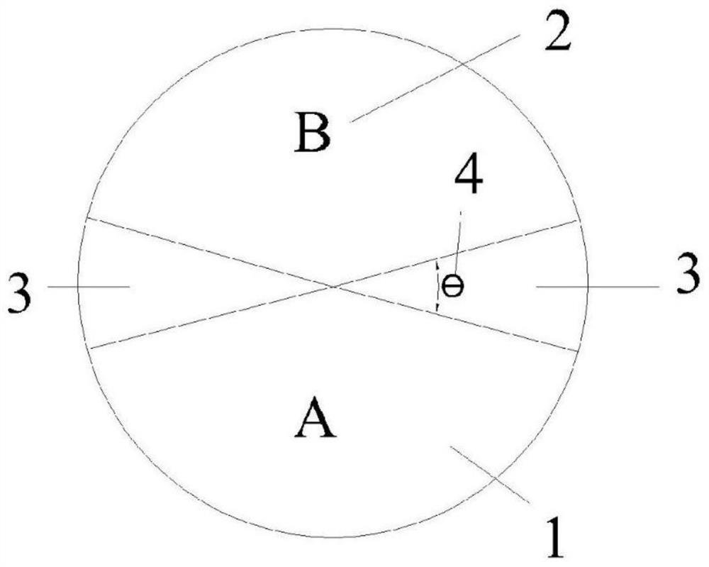
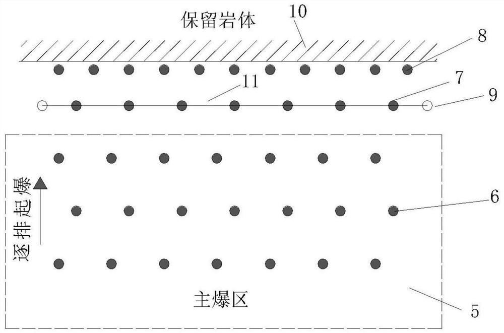
[0045] figure 1 A structural diagram of the energy-gathering-energy-dissipating blaster is given, including cavity A1 for explosives, cavity B2 for explosives or energy-absorbing substances, energy-gathering chamber 3 for water or energy-absorbing substances, and the optimal energy-gathering angle of 15 ° ~ 45 ° gathering angle 4. figure 2 A schematic diagram of the blast hole layout is given, including the main blast area 5, the main blast area blast hole 6, the wave trap hole 7, the energy dissipation hole 8, the empty hole 9, the retained rock mass 10, and the directional fracture 11.

Embodiment 2

[0047] The following description is based on the wave choke-energy dissipation method of reducing the harmful effect blasting method based on embodiment 1, comprising the following steps:

[0048] Step 1: Arranging blastholes 6 in the main explosion zone, such as figure 2 shown.

[0049] As a preferred solution, vertical drilling, the hole depth is 13m, the diameter of the blast hole 6 is 120mm, the distance between the blast hole 6 is 5m, and the row spacing is 4.3m.

[0050] Step 2: Arrange the choke holes 7, the row distance between the choke holes 7 and the energy dissipation holes 8 is 0.75 times the row distance of the blast hole 6 in the main blast zone, and the hole depth is 1.1 times that of the blast hole 6 in the main blast zone, as figure 2 shown.

[0051] As a preferred solution, vertical drilling, hole depth 14.5m, blast hole 7 diameter 120mm, blast hole 7 spacing 5m, choke hole 7 and the blast hole row spacing in the main blast area adjacent to it 4.3m, chok...


PUM


Abstract

The invention discloses a blasting method for reducing harmful effects based on choke-energy dissipation, which belongs to the technical field of mining construction and comprises the following steps: sequentially arranging blastholes in the main blast zone, wave choke holes, energy dissipation holes, empty holes on the working face hole; prepare the energy-gathering-energy-dissipating blaster; put water, explosives, and rubber pads into the blaster; put ordinary explosives into the main gun hole, and put the blaster with energy-gathering effect into the choke hole, which has energy dissipation The blaster is loaded into the energy dissipation hole; the water gun mud is sealed; and the micro-differential detonation. In the present invention, multiple methods such as directional crack wave damming formed by detonation of the choke hole first, directional energy absorption of the blaster in the energy dissipation hole, air hole suppressing wing crack initiation, displacement of the space to guide the explosion energy propagation of the energy dissipation hole and other methods are superimposed and applied, greatly greatly Reduces blast hazard effects.

Description

technical field [0001] The invention relates to a blasting method, in particular to a blasting method for reducing the harmful effect of explosion, and belongs to the technical field of mining construction. Background technique [0002] Because the blasting method has the advantages of convenience, quickness and economy, it is widely used in national infrastructure construction. However, ordinary blasting methods will produce harmful effects such as vibration, cracks, and flying stones, which will reduce the stability of surrounding rocks and cause damage to surrounding structures. Although the popular pre-splitting blasting and smooth blasting can improve the regularity of the surrounding rock to a certain extent, they cannot avoid damage to the surrounding rock and surrounding structures due to the random release of explosion energy and the random expansion of cracks. Contents of the invention [0003] The main purpose of the present invention is to provide a blasting m...

Claims


Application Information

Patent Timeline
Patent Type & Authority Patents(China)
IPC IPC(8): F42D1/00F42D5/045
CPCF42D1/00F42D5/045Y02A10/11
Inventor 苏洪龚悦李凯李杨文博汪灿冯伟曹帅
Owner ANHUI UNIV OF SCI & TECH
Why Eureka
Try Eureka