Integrated hydraulic module of an electrohydraulic servo brake

A hydraulic servo and hydraulic module technology, applied in the direction of brakes, brake transmissions, transmissions, etc., can solve the problems of insufficient durability, unreliable risk of wear and function loss, etc.

Active Publication Date: 2020-05-26
ROBERT BOSCH GMBH
View PDF10 Cites 1 Cited by
  • Summary
  • Abstract
  • Description
  • Claims
  • Application Information

AI Technical Summary

Problems solved by technology

[0009] However, this known solution has a certain number of disadvantages
Firstly, the pistons are subject to deformations that risk creating surface fracture sites at the level of the anodization
The piston and its flange are unr...

Method used


Image

  • Integrated hydraulic module of an electrohydraulic servo brake
  • Integrated hydraulic module of an electrohydraulic servo brake
  • Integrated hydraulic module of an electrohydraulic servo brake

Examples


Embodiment Construction

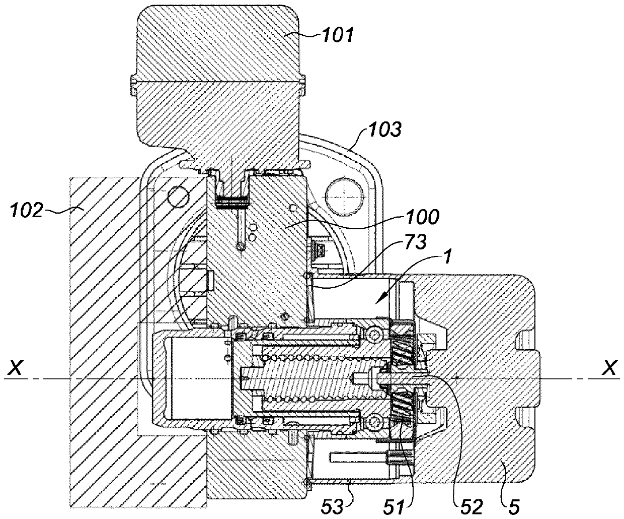
[0029] according to figure 1 The present invention has as subject a hydraulic module 1 for a hydraulic block 100 , which is covered by a brake fluid reservoir 101 which supplies the hydraulic block 100 . The control unit 102 of the module is fastened on the side of the hydraulic block 100 .

[0030] The hydraulic block 100 is traversed by a hydraulic module 1 which is externally fastened on the side of the block 1 covered by its electric motor 5 (its housing), which is itself fastened separately on the On this side of the hydraulic block 100 .

[0031] The hydraulic block 100 constructed in this way is fastened to the dash panel of the vehicle via a support plate 103 , which is carried by the rear side of the hydraulic block 100 according to the installation orientation of the block in the vehicle.

[0032] Lines traverse the hydraulic block 100 for exchanging brake fluid between the reserve device 101 and the hydraulic block 100 and between the latter and the brake circuit ...


PUM


Abstract

A hydraulic module having a cylinder (2) which accommodates a piston (3) which delimits a chamber (4) which receives the brake fluid. The piston (3) is connected to the electric motor (5) of the module (1) by way of a recirculating ball spindle (6), the core (61) of which is connected fixedly to the piston (3) which itself is guided by way of needles (21) which are parallel to the axis (xx) of thepiston (3) and with which notches (351) on the circumference of the piston (3) interact. The piston (3) is a piece which is formed from a cylindrical body (32) made from anodized aluminium and an outer ring (35) which is made from steel, is positively mounted on the edge (34) of the piston and is provided with notches (351) with a cross section which corresponds to the useful cross section of theneedles (21).

Description

technical field [0001] The subject of the invention is an integrated hydraulic module of an electrohydraulic servo brake comprising the following: [0002] - the cylinder, which houses the piston, which delimits the chamber, which receives the brake fluid for supplying the brake cycle according to the braking command, [0003] - Among them, the piston is connected with the electric motor of the module through the ball running screw, and the ball running screw controls the translational movement of the piston through its rotational movement, [0004] * where the threaded core of the lead screw is fixedly connected to the piston, the piston itself is locked in rotation but free in translation according to the axis in that the piston is guided by a needle parallel to the axis of the piston and cooperate with the recess on the periphery of the piston, and [0005] * The threaded sleeve of the ball-running screw is driven in rotation by an electric motor. Background technique ...

Claims


Application Information

Patent Timeline
IPC IPC(8): B60T13/74
CPCB60T13/745B60T13/746F16H25/2214F15B15/1414F15B7/08F15B15/1471F05C2201/021F05C2201/0448
Inventor M.琼路易斯A.阿利利
Owner ROBERT BOSCH GMBH
Why Eureka
Try Eureka