Lifting anti-falling operating platform for constructional engineering

An operation platform and construction engineering technology, which is applied in the direction of construction, building structure, house structure support, etc., can solve the problem of large tensile force of the insurance wire rope

Inactive Publication Date: 2020-05-29
左雪云
View PDF0 Cites 11 Cited by
  • Summary
  • Abstract
  • Description
  • Claims
  • Application Information

AI Technical Summary

Problems solved by technology

[0003] The purpose of the present invention is to solve the defect in the prior art that the insurance wire rope bears too much tension during the platform's descending and braking process, and propose a lifting and anti-falling operation platform for construction engineering

Method used


Image

  • Lifting anti-falling operating platform for constructional engineering
  • Lifting anti-falling operating platform for constructional engineering
  • Lifting anti-falling operating platform for constructional engineering

Examples


Embodiment 1

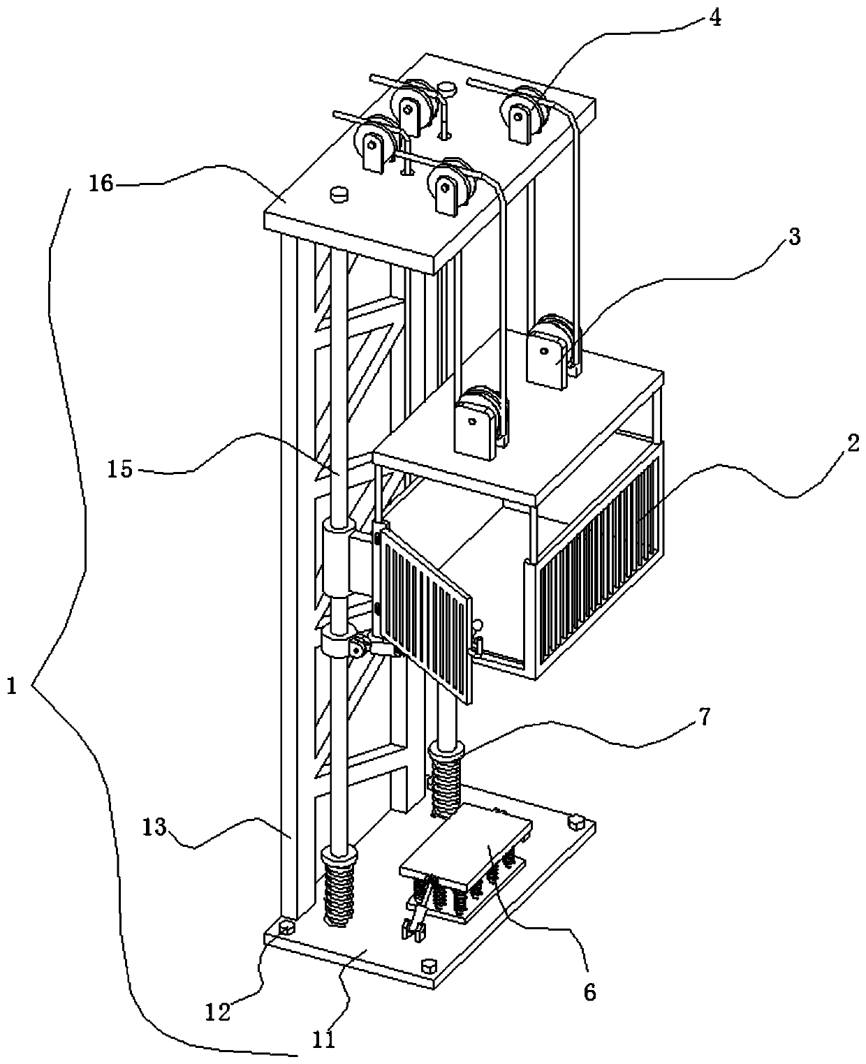
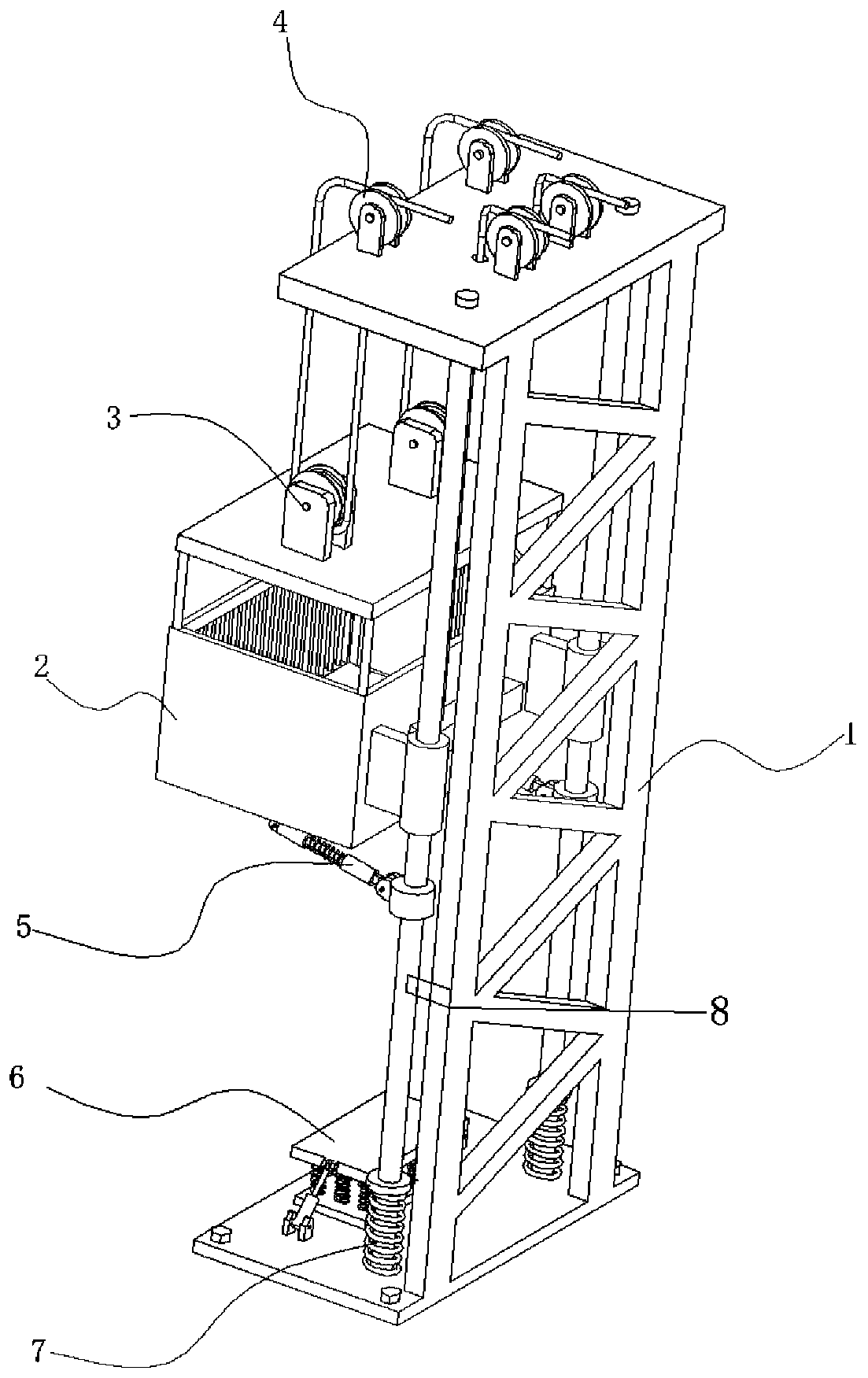
[0037] refer to Figure 1-3, a lifting anti-fall operation platform for construction engineering, including a mounting mechanism 1, the mounting mechanism 1 includes a base 11, a number of anchor bolts 12, a mounting frame 13, two guide rail columns 15 and a top seat 16, the base 11 passes through the anchor bolts 12 is fixedly installed on the ground, the bottom of the mounting frame 13 is fixedly mounted on the base 11, the top of the mounting frame 13 is fixedly connected with the top base 16, and two guide rail posts 15 are fixedly installed between the top base 16 and the base 11, and two Guide rail columns 15 are arranged in parallel;

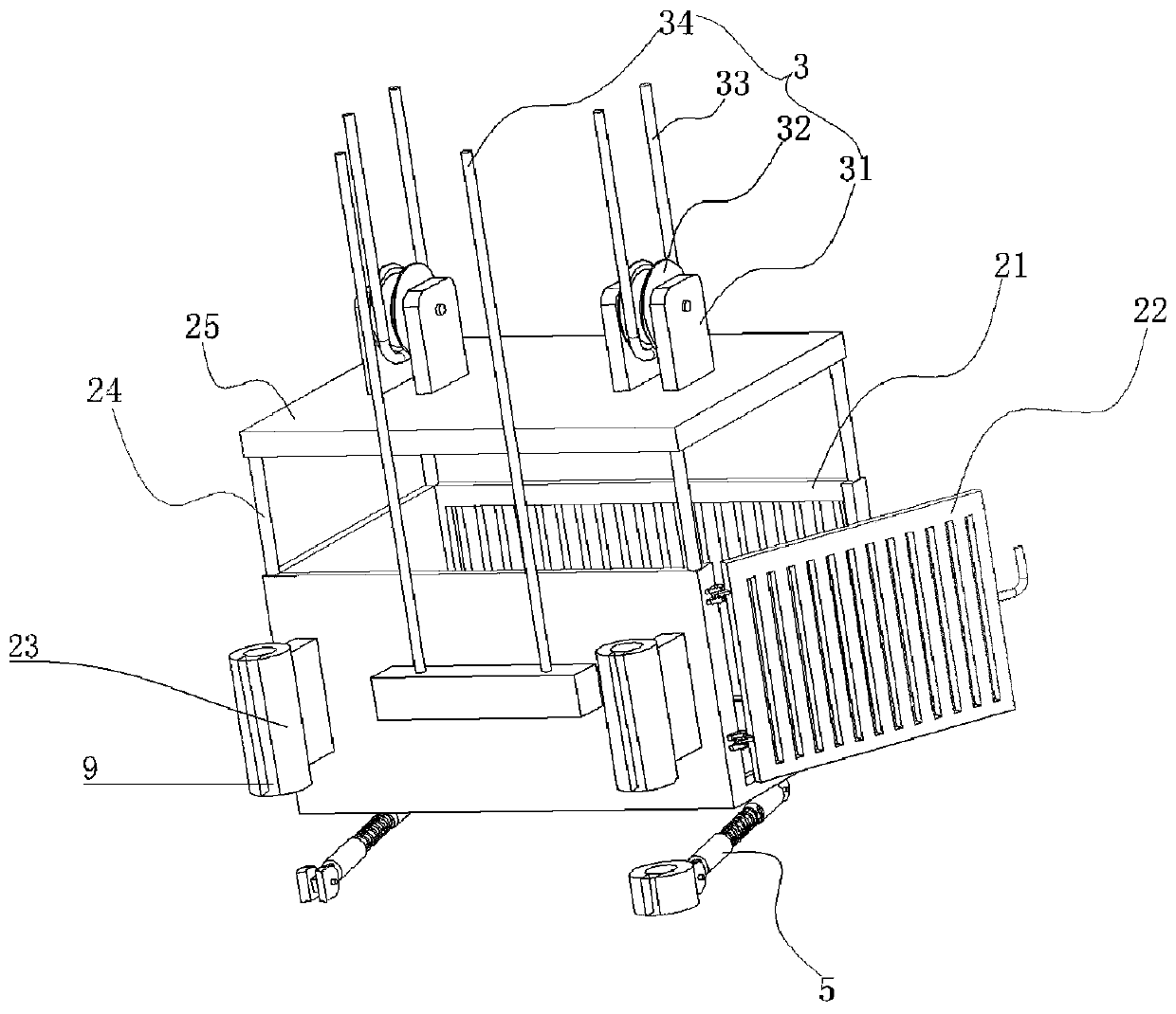
[0038] The platform assembly 2 is installed on the rail column 15, and the platform assembly 2 includes a support platform 21, a protective door 22, two sliding seats 23, several connecting rods 24 and a top plate 25, and the two sliding seats 23 are respectively sleeved on the corresponding rail column 15. on, and is slidably connected ...

Embodiment 2

[0042] refer to Figure 1-4 As another preferred embodiment of the present invention, the difference from Embodiment 1 is that a guide mechanism 4 corresponding to the lifting mechanism 3 is installed on the top of the top seat 16, and the guide mechanism 4 includes two first mounting seats 41, two A first guide wheel 42, two second mounts 43 and two second guide wheels 44, the two first mounts 41 are fixedly mounted on the top of the top seat 16, and parallel to each other, the two first guide wheels 42 Rotately connect with the corresponding first mounting base 41 through pin shaft; Two mounting bases 43 are rotationally connected;

[0043] The first lifting cable 33 is set on the corresponding first guide wheel 42, and is connected with the first guide wheel 42 in transmission; the second lifting cable 34 is set on the corresponding second guide wheel 44, and is connected with the second guide wheel 44 Drive connection. The first guide wheel 42 and the second guide wheel...

Embodiment 3

[0045] refer to Figure 1-5 , as another preferred embodiment of the present invention, the difference from Embodiment 1 or Embodiment 2 is that two brake mechanisms 5 are installed on the bottom of the support platform 21, and the brake mechanism 5 includes a brake ring 51, a first set Seat 52, first spring 53, sleeve rod 54, push rod 55 and second sleeve seat 56, brake ring 51 is sleeved on the corresponding guide rail post 15, and is slidably connected with guide rail post 15; the first sleeve seat 52 One end of one end is rotationally connected with the brake ring 51 through a hinge, and the two ends of the sleeve rod 54 are inserted into the first sleeve seat 52 and the second sleeve seat 56 respectively, and the sleeve rod 54 is connected to the first sleeve seat 52 and the second sleeve seat 56. Both are slidingly connected; the first spring 53 is sleeved on the sleeve rod 54, the push rod 55 is rotatably connected with the second sleeve 56 through a hinge, the push rod...


PUM


Abstract

The invention relates to the technical field of lifting platforms for constructional engineering, in particular to a lifting anti-falling operating platform for constructional engineering. The liftinganti-falling operating platform for constructional engineering comprises an installation mechanism, wherein the installation mechanism comprises a base, a plurality of foundation bolts, an installation frame, two guide rail columns and a top seat; a platform assembly is arranged on the guide rail columns, and comprises a support platform, a protection door, two sliding seats, a plurality of connecting rods and a top plate; the two sliding seats respectively sleeve the corresponding guide rail columns and are slidably connected with the guide rail columns; the support platform is fixedly arranged on the side walls of the sliding seats; the protection door is rotatably connected with the support platform through a hinge; the connecting rods are welded to the top part of the support platform; and the top plate is welded to the top parts of the connecting rods. According to the lifting anti-falling operating platform for constructional engineering provided by the invention, the tensile force of a steel wire rope in the braking process can be greatly reduced, so that the service life and the use safety of the steel wire rope are improved.

Description

technical field [0001] The invention relates to the technical field of lifting platforms for construction engineering, in particular to a lifting and anti-falling operation platform for construction engineering. Background technique [0002] Building construction refers to the production activities in the implementation stage of engineering construction. It is the construction process of various buildings. It can also be said to be the process of turning various lines on the design drawings into real objects at designated places; at present, the existing technology The lifting platforms of construction machinery in China are generally equipped with safety mechanisms. These safety mechanisms are oblique iron and eccentric wheel clamping mechanisms controlled by traction safety wire ropes. The mechanism uses two secondary wire ropes; when the lifting platform rises or falls During the process, the platform reaches the target position at a certain speed, and braking operation i...

Claims


Application Information

Patent Timeline
Patent Type & Authority Applications(China)
IPC IPC(8): E04G1/15E04G1/18E04G1/24E04G5/00
CPCE04G1/15E04G1/18E04G1/24E04G5/001E04G2005/008
Inventor 左雪云
Owner 左雪云
Why Eureka
Try Eureka