Wind power generation device with protective function

A technology for wind power generation devices and protection functions, applied in the field of new energy equipment, can solve the problems of reduced practicality of wind power generation devices, excessive generation inside the nacelle, and influence on the operation of other facilities in the nacelle, so as to improve practicability, safety, stability and The effect of efficient power generation

Inactive Publication Date: 2020-05-29
南京振轩新能源科技有限公司
View PDF0 Cites 10 Cited by
  • Summary
  • Abstract
  • Description
  • Claims
  • Application Information

AI Technical Summary

Problems solved by technology

[0003] During the operation of the existing wind power generation device, the rotational speed of the rotating shaft is affected by the external wind force. Therefore, when the external wind force is too strong, the brake disc is usually used inside the nacelle to reduce the rotational speed of the blades and the rotating shaft. However, during the process of reducing the rotational speed , since the brake disc is braked by friction, it will not only cause excessive heat inside the cabin, which will affect the operation of other facilities in the cabin, but will also lead to a decrease in the power generation of the wind turbine, which in turn will lead to the existing wind power Reduced availability of generators

Method used


Image

  • Wind power generation device with protective function
  • Wind power generation device with protective function
  • Wind power generation device with protective function

Examples


Embodiment Construction

[0025] The present invention is described in further detail now in conjunction with accompanying drawing. These drawings are all simplified schematic diagrams, which only illustrate the basic structure of the present invention in a schematic manner, so they only show the configurations related to the present invention.

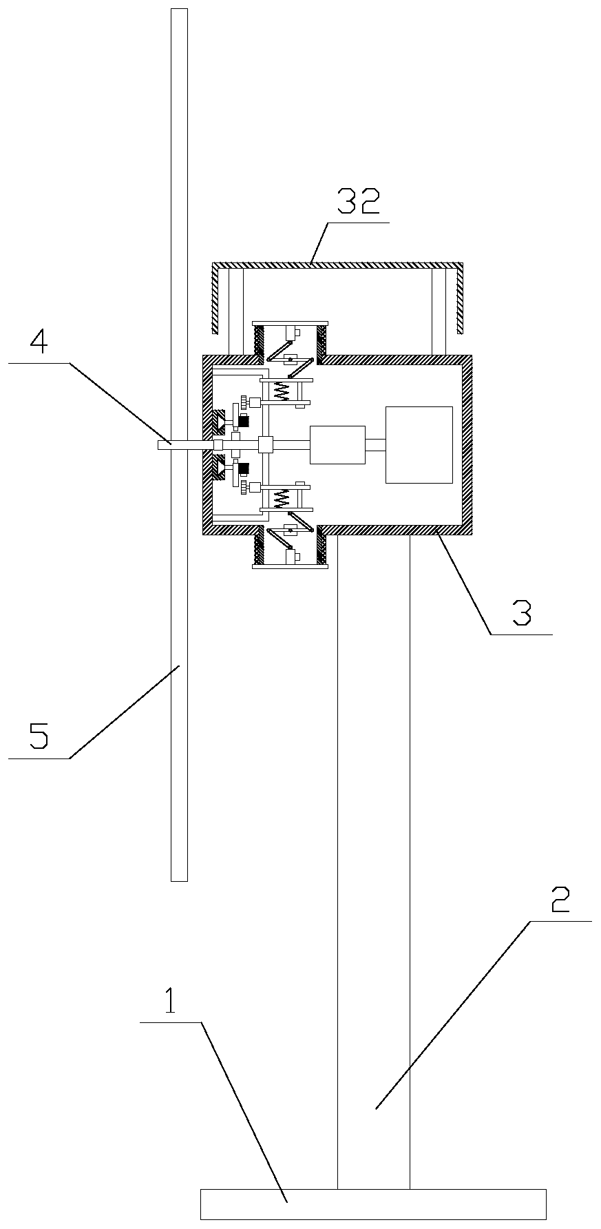
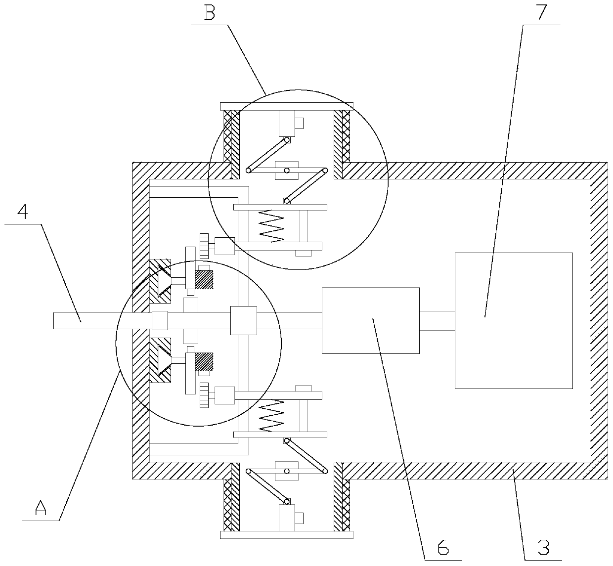
[0026] Such as figure 1 As shown, a wind power generation device with protection function includes a base 1, a tower 2, a nacelle 3, a hub 4 and several blades 5, the nacelle 3 is arranged above the base 1 through the tower 2, and the hub One end of 4 is arranged in the nacelle 3, the fan blades 5 are evenly distributed in the circumferential direction on the other end of the hub 4, and the nacelle 3 is provided with a PLC and a power generation device;

[0027] In this wind power generation device, the position of the base 1 is fixed, and the nacelle 3 is supported by the tower frame 2. When the wind blows on the blades 5, the blades 5 are driven to rotate, ...


PUM


Abstract

The invention relates to a wind power generation device with the protective function. The wind power generation device comprises a base, a tower frame, an engine room, a wheel hub and a plurality of fan blades; a power generation device comprises a speed-increasing gearbox, a first electric generator, a reducing mechanism and a plurality of heat dissipating mechanisms; the reducing mechanism comprises a circular ring, a support component, a plurality of convex plates, a plurality of convex teeth and a plurality of air cylinders; each of the heat dissipating mechanisms comprises a heat dissipating pipe, a cover plate, a filter screen, a driving component, a telescopic component, a second electric generator and a gear; and the telescopic component comprises a bracket, a sliding plate, a movable plate, a spring and a limiting unit. Through cooperative operation of the reducing mechanism and the heat dissipating mechanisms, the wind power generation device can reduce the rotary speed of agear when the wind power is stronger and does work to the second electric generator through gear rotation for additional power generation; and at the same time, the cover plate is separated from the the heat dissipating pipes, so that the engine room can conveniently carry out ventilation and heat dissipation, and the wind power generation device generates electricity in a safe, stable and efficient manner to improve the practicality of the wind power generation device.

Description

technical field [0001] The invention relates to the field of new energy equipment, in particular to a wind power generating device with a protection function. Background technique [0002] A wind turbine is a power device that converts wind energy into mechanical work, which drives the rotor to rotate, and finally outputs alternating current. Wind turbines are generally composed of components such as wind rotors, generators (including devices), steering devices (tail fins), towers, speed-limiting safety mechanisms, and energy storage devices. The working principle of a wind turbine is relatively simple. The wind rotor rotates under the action of the wind, which converts the kinetic energy of the wind into the mechanical energy of the wind rotor shaft, and the generator rotates to generate electricity under the drive of the wind rotor shaft. In a broad sense, wind energy is also solar energy, so it can also be said that a wind generator is a thermal energy utilization genera...

Claims


Application Information

Patent Timeline
Patent Type & Authority Applications(China)
IPC IPC(8): F03D7/04F03D80/60F03D9/25F03D15/00
CPCF03D7/0244F03D7/0276F03D7/047F03D9/25F03D15/00F03D80/60Y02E10/72
Inventor 汤在英
Owner 南京振轩新能源科技有限公司
Why Eureka
Try Eureka