Device and method for adjusting and controlling wear dust distribution of pantograph-catenary contact pair

A technology of regulating device and contact pair, which is used in measuring devices, using mechanical devices, testing electrical devices in transportation, etc., can solve problems such as mechanical wear of friction pairs, achieve balance, improve severe friction and wear, and reduce roughness. Effect

Active Publication Date: 2021-08-24
SOUTHWEST JIAOTONG UNIV
View PDF6 Cites 0 Cited by
  • Summary
  • Abstract
  • Description
  • Claims
  • Application Information

AI Technical Summary

Problems solved by technology

[0004] In view of the above-mentioned deficiencies in the prior art, the pantograph-catenary contact pair wear debris distribution control device and method provided by the present invention solve the existing problem of serious mechanical wear of the friction pair caused by the continuous increase of train speed and load

Method used


Image

  • Device and method for adjusting and controlling wear dust distribution of pantograph-catenary contact pair
  • Device and method for adjusting and controlling wear dust distribution of pantograph-catenary contact pair
  • Device and method for adjusting and controlling wear dust distribution of pantograph-catenary contact pair

Examples


Embodiment 1

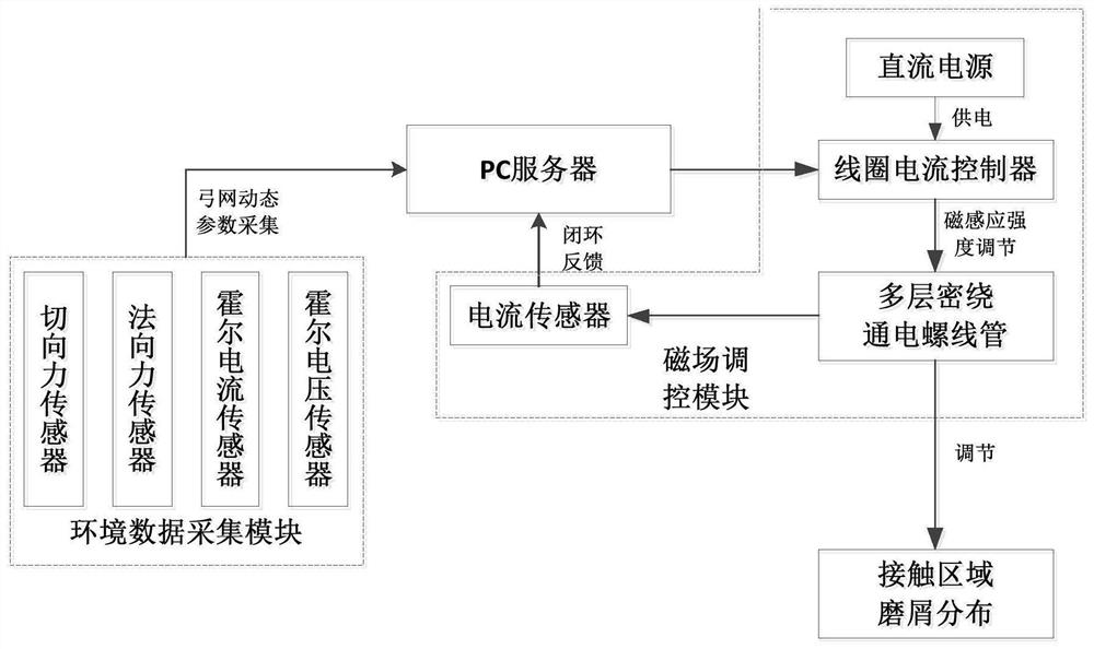
[0060] Such as figure 1 As shown, a pantograph-catenary contact wear debris distribution control device includes a magnetic field control module, an environmental data acquisition module and a PC server;

[0061] Both the magnetic field control module and the environmental data acquisition module are connected to the PC server;

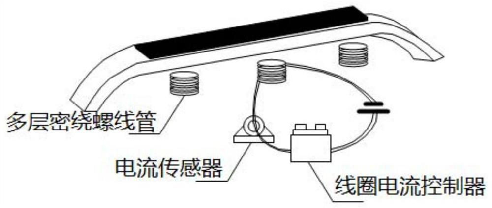
[0062] The magnetic field control module includes a current sensor, a coil current controller, a DC power supply and a multi-layer close-wound solenoid, and the current sensor and the coil current controller are both connected to the PC server, and the DC power supply is connected to the Coil current controller connection;

[0063] The environmental data acquisition module includes a force sensor, a Hall current sensor and a Hall voltage sensor all connected to the PC server.

[0064] The magnetic field control module in the embodiment of the present invention is used to generate the corresponding magnetic induction intensity in the contact area of ...

Embodiment 2

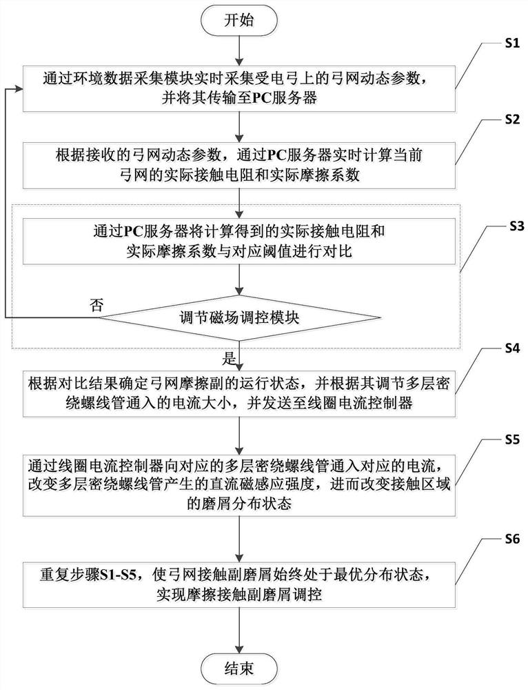
[0076] Such as image 3 Shown: a pantograph-catenary contact wear debris distribution control method, including the following steps:

[0077] S1. Collect the pantograph-catenary dynamic parameters on the pantograph in real time through the environmental data acquisition module, and transmit them to the PC server;

[0078] S2. According to the received pantograph-catenary dynamic parameters, calculate the actual contact resistance and actual friction coefficient of the current pantograph-catenary in real time through the PC server;

[0079] S3. Comparing the calculated actual contact resistance and actual friction coefficient with the corresponding threshold through the PC server, and then judging whether to adjust the magnetic field control module;

[0080] If yes, enter step S4;

[0081] If not, return to step S1;

[0082] S4. Determine the operating state of the pantograph-catenary friction pair according to the comparison result, and adjust the current size of the multi-...


PUM


Abstract

The invention discloses a pantograph-catenary contact wear debris distribution control device and method. The device comprises a magnetic field control module, an environmental data collection module and a PC server; the magnetic field control module and the environmental data collection module are both connected to the PC server; the PC The server controls the current intensity of the magnetic field control module according to the data of the environmental data acquisition module, so that a specific magnetic induction intensity is generated in the contact area of ​​the pantograph-catenary friction pair, so that the distribution of wear debris in the contact area is in an optimal state; the present invention reduces the friction coefficient, improves the The surface roughness realizes the mechanical and electrical balance of the pantograph-catenary system, improves the severe mechanical wear of the pantograph slide plate and the catenary wire, and also improves the energy transmission efficiency and electrical contact characteristics of the pantograph-catenary system, and the structure is simple and the effect is Significant, with strong practical value and promotion value.

Description

technical field [0001] The invention belongs to the field of magnetic field control technology and pantograph-catenary technology, and in particular relates to a pantograph-catenary contact wear debris distribution control device and method. Background technique [0002] The electrified locomotive obtains electric energy from the catenary wire through the pantograph slide plate, so the stability of the pantograph-catenary system directly affects the current quality and running state of the train. With the advancement of high-speed trains, the mechanical wear of the pantograph-catenary contact pair continues to increase, which greatly increases the maintenance cost of the pantograph-catenary system, reduces the service life of the slide plate and wires, and may even cause pantograph-catenary accidents in severe cases, resulting in irreparable personnel property loss. [0003] The carbon slide has a layered structure, which has occupied the railway market for a long time with...

Claims


Application Information

Patent Timeline
Patent Type & Authority Patents(China)
IPC IPC(8): G01R31/00G01R27/20G01N19/02G01M13/00
CPCG01M13/00G01N19/02G01R27/205G01R31/008
Inventor 吴广宁何志江王虹魏文赋杨泽锋高国强王潇邓磊倪子然
Owner SOUTHWEST JIAOTONG UNIV
Why Eureka
Try Eureka