Oil transportation heat management system design method for controlling temperature rise of fuel oil of high-speed aircraft

A technology of management system and design method, applied in computer-aided design, design optimization/simulation, calculation, etc., can solve the problems of over-temperature failure of oil-passing valve, reducing fuel loading space, over-temperature of engine wall, etc., to reduce fuel temperature , reduce the risk of cavitation, reduce the effect of boost pressure

Active Publication Date: 2020-05-29
BEIJING AEROSPACE TECH INST
View PDF6 Cites 2 Cited by
  • Summary
  • Abstract
  • Description
  • Claims
  • Application Information

AI Technical Summary

Problems solved by technology

[0004] The present invention provides a design method for the thermal management system of fuel delivery for controlling the fuel temperature rise of high-speed aircraft, which can solve the problems of cavitation and overheating of fuel valves in high-speed aircraft fuel pumps in the prior art without reducing the fuel loading space. Technical problems of failure and engine wall overheating

Method used

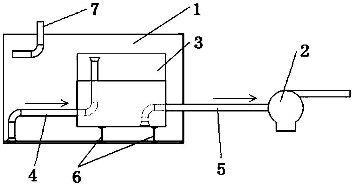

Image

  • Oil transportation heat management system design method for controlling temperature rise of fuel oil of high-speed aircraft
  • Oil transportation heat management system design method for controlling temperature rise of fuel oil of high-speed aircraft
  • Oil transportation heat management system design method for controlling temperature rise of fuel oil of high-speed aircraft

Examples


Embodiment Construction

[0030] It should be noted that, in the case of no conflict, the embodiments in the present application and the features in the embodiments can be combined with each other. The following will clearly and completely describe the technical solutions in the embodiments of the present invention with reference to the accompanying drawings in the embodiments of the present invention. Obviously, the described embodiments are only some, not all, embodiments of the present invention. The following description of at least one exemplary embodiment is merely illustrative in nature and in no way taken as limiting the invention, its application or uses. Based on the embodiments of the present invention, all other embodiments obtained by persons of ordinary skill in the art without creative efforts fall within the protection scope of the present invention.

[0031] It should be noted that the terminology used here is only for describing specific implementations, and is not intended to limit t...


PUM


Abstract

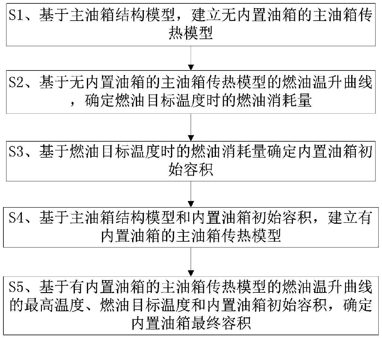
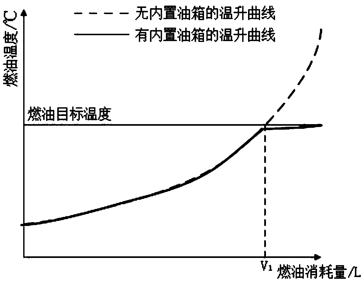
The invention provides an oil transportation heat management system design method for controlling the temperature rise of fuel oil of a high-speed aircraft, and the method comprises the steps: building a main oil tank heat transfer model without a built-in oil tank based on a main oil tank structure model; based on the fuel temperature rise curve of the main oil tank heat transfer model without the built-in oil tank, determining the fuel consumption at the fuel target temperature; determining the initial volume of the built-in oil tank based on the fuel consumption at the target fuel temperature; based on the main oil tank structure model and the initial volume of the built-in oil tank, establishing a main oil tank heat transfer model of the built-in oil tank; and determining the final volume of the built-in oil tank based on the highest temperature of the fuel oil temperature rise curve of the main oil tank heat transfer model with the built-in oil tank, the fuel oil target temperature and the initial volume of the built-in oil tank. The method can effectively reduce the temperature of the fuel at the flight tail section of the long-endurance high-speed aircraft, and can achieve the effects of reducing the cavitation risk of a fuel pump, reducing the pressurization pressure of a fuel tank, reducing the design difficulty of fuel passing equipment, increasing the available fuelheat sink of an engine and the like.

Description

technical field [0001] The invention relates to the technical field of high-speed aircraft fuel delivery and thermal management, in particular to a design method for a fuel delivery thermal management system for controlling the temperature rise of high-speed aircraft fuel. Background technique [0002] At present, the fuel tank body of the existing high-speed aircraft is not only used for storing fuel oil, but also plays the role of carrying the aircraft. Due to the high flight speed and severe aerodynamic heating, the temperature of the fuel in the cabin continues to rise after a long flight; especially at the end of the flight, the amount of fuel decreases and the temperature rise of the fuel accelerates. Elevated fuel temperature will make the pump inlet more prone to cavitation, and will also increase the risk of overtemperature failure of the oil passage valve. For high-speed aircraft that use fuel for active engine cooling, increased fuel temperature also increases th...

Claims


Application Information

Patent Timeline
Patent Type & Authority Applications(China)
IPC IPC(8): G06F30/15G06F30/20G06F119/08
CPCY02T50/40
Inventor 于鹏汪颖向安定邵文清谢宗齐石峰梁磊
Owner BEIJING AEROSPACE TECH INST
Why Eureka
Try Eureka