System and method for acquiring working voltage of crystal oscillator, and chip

A technology of crystal oscillator and working voltage, applied in CAD circuit design and other directions, can solve the problem of high power consumption of crystal oscillator, achieve the effect of stabilizing oscillation frequency, reducing chip power consumption and reducing overall power consumption

Active Publication Date: 2020-05-29
EDGELESS SEMICON CO LTD OF ZHUHAI +1
View PDF5 Cites 1 Cited by
  • Summary
  • Abstract
  • Description
  • Claims
  • Application Information

AI Technical Summary

Problems solved by technology

[0003] The object of the present invention is to overcome the technical problem that crystal oscillators consume large power in the prior art, and provide a system, method, and chip

Method used


Image

  • System and method for acquiring working voltage of crystal oscillator, and chip
  • System and method for acquiring working voltage of crystal oscillator, and chip
  • System and method for acquiring working voltage of crystal oscillator, and chip

Examples


specific Embodiment 1

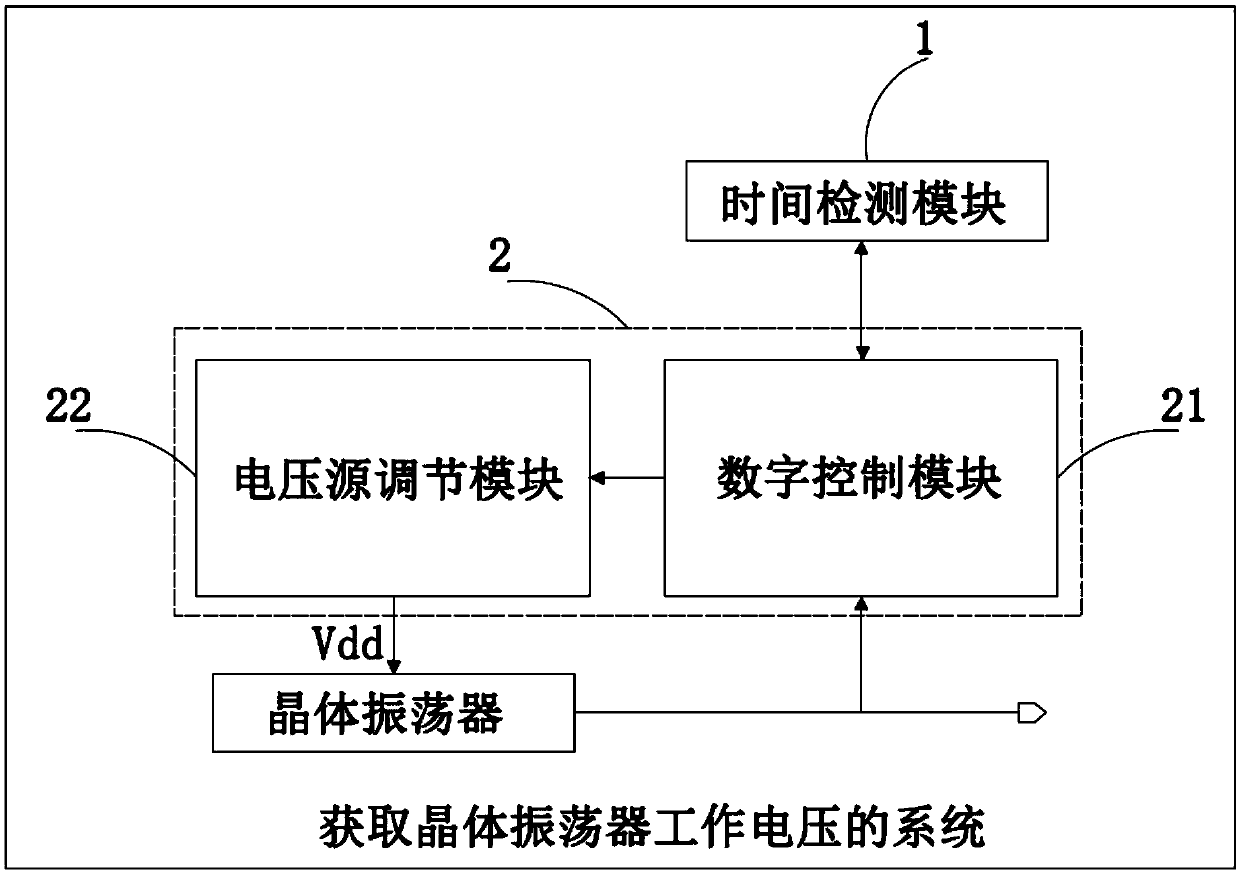
[0026] Such as figure 1 As shown, a system for obtaining the working voltage of a crystal oscillator includes a time detection module 1, a control circuit 2,

[0027] The time detection module 1 detects the dead time of the crystal oscillator, the time detection module adopts a controllable clock, and the controllable clock can accurately detect the dead time of the crystal oscillator;

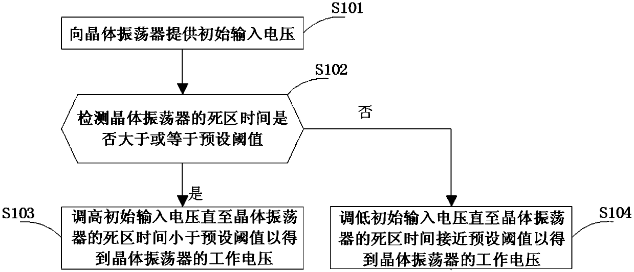
[0028] The control circuit 2 is connected to the time detection module 1 and the crystal oscillator, and provides an input voltage to the crystal oscillator according to the dead time detected by the time detection module 1, wherein when the crystal When the dead time of the oscillator is greater than or equal to the preset threshold, repeating the steps of increasing the input voltage of the crystal oscillator and detecting the dead time of the crystal oscillator until the dead time of the crystal oscillator is less than the preset threshold The preset threshold to obtain the operating volta...

specific Embodiment 2

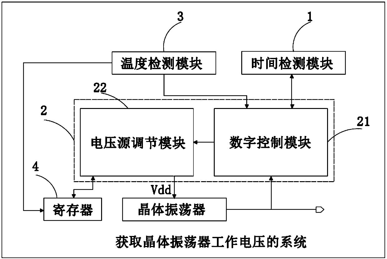
[0041] Such as image 3 As shown, the system for obtaining the operating voltage of the crystal oscillator in this embodiment has the same time detection module 1 and control circuit 2 as in the first embodiment. The difference from the first embodiment is that due to the working environment of the crystal oscillator The temperature change is uncontrollable, and in this embodiment also includes a temperature detection module 3, a register 4,

[0042] The temperature detection module 3 detects the change of the ambient temperature of the crystal oscillator, wherein when the change of the ambient temperature of the crystal oscillator exceeds the warning range, the control circuit 2 repeats the adjustment according to the dead time of the crystal oscillator. The input voltage of the crystal oscillator to obtain the operating voltage of the crystal oscillator, the register 4 stores and memorizes the operating voltage of the crystal oscillator readjusted by the control circuit 2 wh...


PUM


Abstract

The invention discloses a system and method for obtaining the working voltage of a crystal oscillator, and a chip. The system comprises a time detection module which detects the dead time of the crystal oscillator; the control circuit is connected with the time detection module and the crystal oscillator; an input voltage is provided for the crystal oscillator according to the dead time detected by the time detection module; and when the dead time of the crystal oscillator is greater than or equal to the preset threshold, the steps of increasing the input voltage of the crystal oscillator anddetecting the dead time of the crystal oscillator are repeated until the dead time of the crystal oscillator is less than the preset threshold to obtain the working voltage of the crystal oscillator.According to the invention, the input voltage of the crystal oscillator is repeatedly adjusted according to the dead time of the crystal oscillator to obtain the working voltage of the crystal oscillator; proper crystal oscillator working voltage is selected through multiple iterations, and under the condition that the crystal oscillator can work normally, the overall power consumption of the circuit is effectively reduced, stable oscillation frequency is output, and the power consumption of a chip is reduced.

Description

technical field [0001] The invention relates to the field of integrated circuit design, in particular to a system, method and chip for obtaining the working voltage of a crystal oscillator. Background technique [0002] In the existing integrated circuit chips, it is very challenging to design a clock generator with extremely low power consumption and high performance that is stable for a long time and is less affected by other factors such as time and external collisions. As a high-precision and high-stability oscillator, the crystal oscillator has high frequency stability and excellent phase noise performance, and can provide highly accurate reference clock signals for various electronic systems, and is widely used in In all kinds of handheld devices and portable electronic products, due to the large current consumption in the working state, it often becomes a limited problem in the field of low-power battery power supply and high precision. After a crystal device is prod...

Claims


Application Information

Patent Timeline
IPC IPC(8): G06F30/30
Inventor 徐以军彭新朝张亮冯玉明黄穗彪王静殷惠萍谢育桦王聪张永光
Owner EDGELESS SEMICON CO LTD OF ZHUHAI
Why Eureka
Try Eureka