Automatic material pushing device

A pusher, automatic technology, applied in forging/pressing/hammer devices, manufacturing tools, forging/pressing/hammering machinery, etc., can solve the problems of low efficiency and large labor

Active Publication Date: 2020-06-02
重庆市桂生机械制造有限公司
View PDF5 Cites 1 Cited by
  • Summary
  • Abstract
  • Description
  • Claims
  • Application Information

AI Technical Summary

Problems solved by technology

[0003] The present invention intends to provide an automatic material pushing device to so

Method used


Image

  • Automatic material pushing device
  • Automatic material pushing device
  • Automatic material pushing device

Examples


Embodiment 1

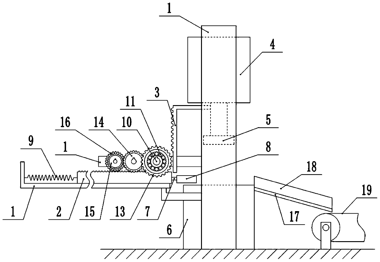
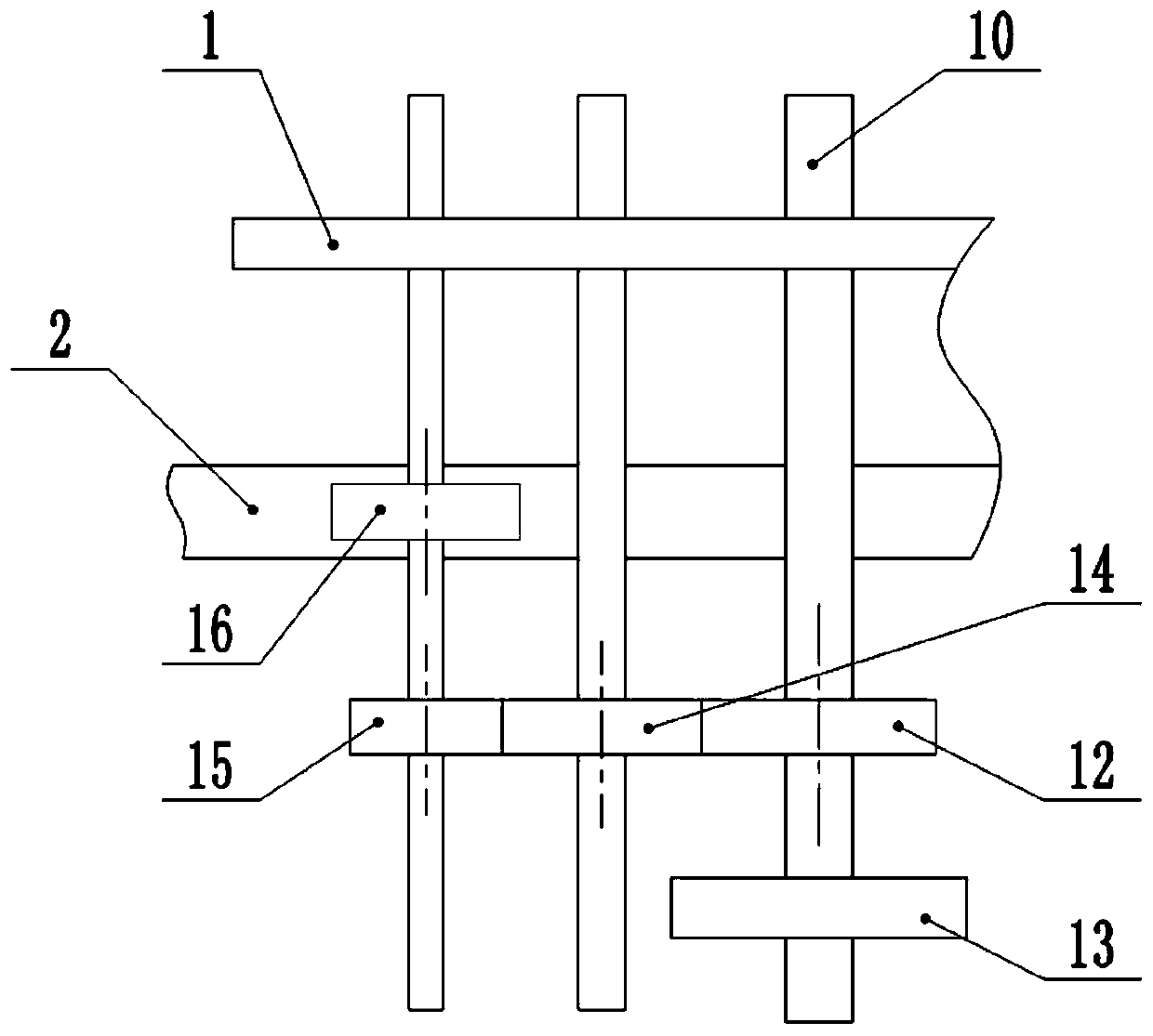
[0031] This embodiment is basically as figure 1 and figure 2 Shown: the automatic pushing device, including frame 1, the first rack 2 arranged horizontally and the second rack 3 arranged vertically, the punching machine 4 is fixedly connected to the frame 1, and the output end of the punching machine 4 is fixed A stamping head 5 is connected, and the stamping head 5 is located above the stamping table 6 .

[0032] The first rack 2 is horizontally slidably connected to the frame 1, the first rack 2 is higher than the stamping table 6, and the gap value between the bottom surface of the first rack 2 and the surface of the stamping table 6 is 3-5mm, this implementation In the example, the gap value is 4mm. The right end of the first rack 2 is fixedly connected with a push rod 7, and the right end of the push rod 7 is fixedly connected with a push plate 8. The push plate 8 is an arc-shaped plate, and the surface of the push plate 8 is coated with a release agent, thereby preven...

Embodiment 2

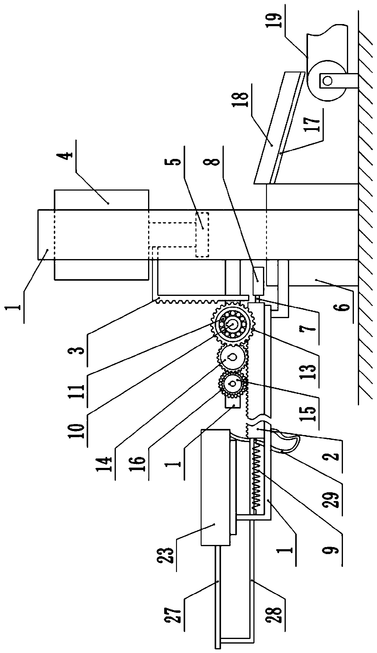
[0038] The difference between this embodiment and Embodiment 1 is that: image 3 and Figure 4 As shown, the inside of the first rack 2 is provided with a cavity, and a first piston 20 is slidably connected in the cavity, and the first piston 20 divides the cavity into a first left chamber 21 and a first right chamber 22, pushing The rod 7 extends into the first right chamber 22 and is connected with the first piston 20 .

[0039] A cylinder body 23 is fixedly connected to the frame 1, and a second piston 24 is slidably connected in the cylinder body 23. The second piston 24 divides the cylinder body 23 into a second left chamber 25 and a second right chamber 26. The second piston 24 is fixedly connected with a piston rod 27, the left end of the piston rod 27 is fixedly connected with a connecting rod 28, and the right end of the connecting rod 28 is fixedly connected with the first rack 2. The second right chamber 26 communicates with the first left chamber 21 through a hos...


PUM


Abstract

The invention relates to the technical field of accessory machining, and particularly discloses an automatic material pushing device. The automatic material pushing device comprises a frame, a first rack and a second rack, wherein the first rack is horizontally and slidably connected to the frame, a push rod is arranged at one end of the first rack, the push rod is fixedly connected with a push plate, the push plate is positioned above a stamping table, an elastic piece is fixedly connected to the other end of the first rack, and the elastic piece is fixedly connected with the frame; the top end of the second rack is fixedly connected with the output end of a stamping machine, the frame is rotatably connected with a horizontally arranged rotating shaft, the rotating shaft is coaxially andfixedly connected with a one-way bearing and a driving gear, and the outer peripheral wall of the one-way bearing is fixedly connected with an outer gear ring capable of being engaged with the secondrack; and the driving gear is engaged with a primary driven gear, the primary driven gear is engaged with a secondary driven gear, and the secondary driven gear is coaxially and fixedly connected witha driving gear engaged with the first rack. According to the automatic material pushing device, the stamping machine is used as a power source to realize automatic material pushing, so that the laboramount of workers is reduced, and the working efficiency is improved.

Description

technical field [0001] The invention relates to the technical field of accessory processing, and specifically discloses an automatic material pushing device. Background technique [0002] In the manufacturing process of accessories, it is necessary to use the punching machine for hot heading of the accessories to be processed, and after the hot heading is completed, the accessories on the stamping table are transferred to the next processing equipment. In the traditional hot upsetting process, workers need to hold tools to clamp the hot upsetting parts away from the stamping table. Since there are hundreds of parts to be processed every day, workers need to manually pick up the hot upsetting parts. Therefore, The workload of the workers is very large and the efficiency is low. Not only that, but the temperature of the accessories during hot heading can reach over 500°C. If you accidentally come into contact with high-temperature accessories during the clamping process, it w...

Claims


Application Information

Patent Timeline
IPC IPC(8): B21J13/14B21J5/00
CPCB21J5/00B21J13/14
Inventor 陈君霞陈贵生
Owner 重庆市桂生机械制造有限公司
Why Eureka
Try Eureka