Conveying mechanism for waste plastic machining machine

A technology for processing machinery and waste plastics, applied to conveyors, conveyor objects, transportation and packaging, etc., can solve the problems of slow processing effect, low processing efficiency, poor pretreatment effect of waste plastics, etc., to reduce manual operations, Improved handling and plastic spatter prevention

Inactive Publication Date: 2020-06-02
肖贤通
View PDF7 Cites 1 Cited by
  • Summary
  • Abstract
  • Description
  • Claims
  • Application Information

AI Technical Summary

Problems solved by technology

[0003] When the conveying mechanism needs to be used, most of the waste plastics are plastics with high hardness. When the conveying mechanism is sent into the processing machine, the processing effect is slow and the processing efficiency is low. The pretreatment effect on waste plastics poor

Method used


Image

  • Conveying mechanism for waste plastic machining machine
  • Conveying mechanism for waste plastic machining machine
  • Conveying mechanism for waste plastic machining machine

Examples


Embodiment 1

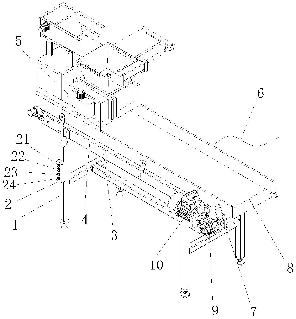
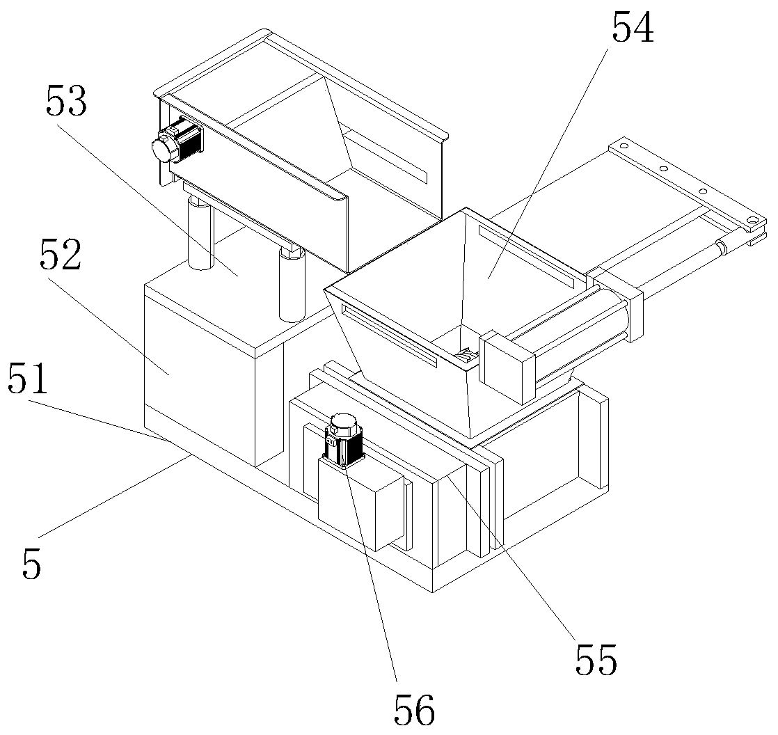
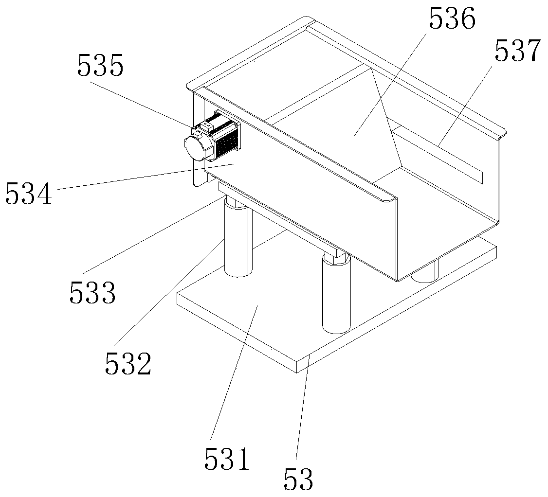
[0031] see figure 1 , the present invention provides a transport mechanism for waste plastic processing machinery through improvement, including a bracket 1, a controller 2, a side plate 3, a guard plate 4, a pretreatment device 5, a power cord 6, a rotating shaft 7, a conveyor belt 8, The reducer 9, the first motor 10, the controller 2 is fixed on the left end of the front end of the bracket 1, and the front end of the controller 2 is sequentially provided with a first switch 21, a second switch 22, a third switch 23 and a fourth switch from top to bottom 24. The controller 2 is electrically connected to the power line 6, the first switch 21 is electrically connected to the first motor 10 through the controller 2, the second switch 22 is electrically connected to the second motor 56 through the controller 2, and the third switch 23 is controlled by The controller 2 is electrically connected with the third motor 535, the fourth switch 24 is electrically connected with the elec...

Embodiment 2

[0038] The present invention provides a conveying mechanism for waste plastic processing machinery through improvement. The push-out plate 536 is fixedly welded with a sliding block in the middle of the front and rear ends. The slide block is inserted into the chute 537. It provides stability, and the guiding effect is good, and there will be no deviation; the left and right ends of the back of the box body 5381 are welded with struts, and the box body 5381 is fixed with the left rear end of the protective frame 534 through the struts, which can be placed in the box body 5381 internal components provide a stable supporting force for the movement; the left end of the middle part of the moving part 5384 is provided with an arc-shaped groove, and the inner width of the arc-shaped groove is larger than the outer diameter of the toggle rod 5383, and the height of the toggle rod 5383 is greater than that of the moving part 5384 The thickness is 1.5cm, which is more convenient for the...


PUM


Abstract

The invention discloses a conveying mechanism for a waste plastic machining machine. The conveying mechanism for the waste plastic machining machine comprises a support. According to the conveying mechanism for the waste plastic machining machine, a pretreatment device is installed at the left end of the top of a protection plate, external charge equipment can be cooperated in the pretreatment device to pretreat conveyed waste plastics, and large plastics are broken to reach a uniform size, and then are conveyed by a conveying belt; a feeding mechanism is arranged at an upper end in the pretreatment device, and controlled by an independent motor, the motor enables a belt wheel to transmit, then a push mechanism installed inside is enabled to carry out reciprocating motion, so that materials are stably pushed off in a reciprocating manner, and cannot be discharged in one process to be treated; and a breaking mechanism is arranged at the right end of the pretreatment device, a stopping mechanism is installed on the breaking mechanism, and when the breaking mechanism receives and breaks the materials, the plastics are liable to splash during breaking, and the stopping mechanism is capable of stopping the top of the breaking mechanism, and preventing the occurrence of safety accidents due to the splashing of the plastics.

Description

technical field [0001] The invention relates to the related field of waste plastic processing, in particular to a conveying mechanism for waste plastic processing machinery. Background technique [0002] Waste plastic is a popular term, it does not refer to waste, old and useless plastic products, most plastic products, especially a large number of disposable ones, the performance of the plastic material itself is not greatly improved after use. Therefore, it is entirely possible to reprocess plastic products with appropriate methods after recycling and use them again. When dealing with waste plastics, special processing machinery is required for processing, and a conveying mechanism needs to be installed in the processing machinery to realize waste recycling. Feed of plastic. [0003] When the conveying mechanism needs to be used, most of the waste plastics are plastics with high hardness. When the conveying mechanism is sent into the processing machine, the processing eff...

Claims


Application Information

Patent Timeline
Patent Type & Authority Applications(China)
IPC IPC(8): B65G47/18B65G69/14B65G65/40
CPCB65G47/18B65G65/40B65G69/14B65G2201/04
Inventor 肖贤通
Owner 肖贤通
Why Eureka
Try Eureka