Compressor and refrigeration equipment
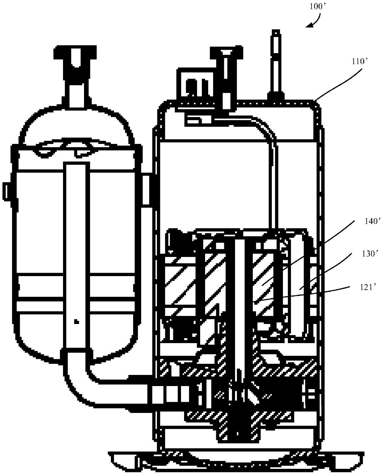
A compressor and motor assembly technology, applied in the field of compressors, can solve the problems of unfavorable vibration, large height of compressor 100', high center of gravity, etc., achieve good vibration noise and efficiency, reduce installation space requirements, and improve air intake channels Effect
- Summary
- Abstract
- Description
- Claims
- Application Information
AI Technical Summary
Problems solved by technology
Method used
Image
Examples
Embodiment 1
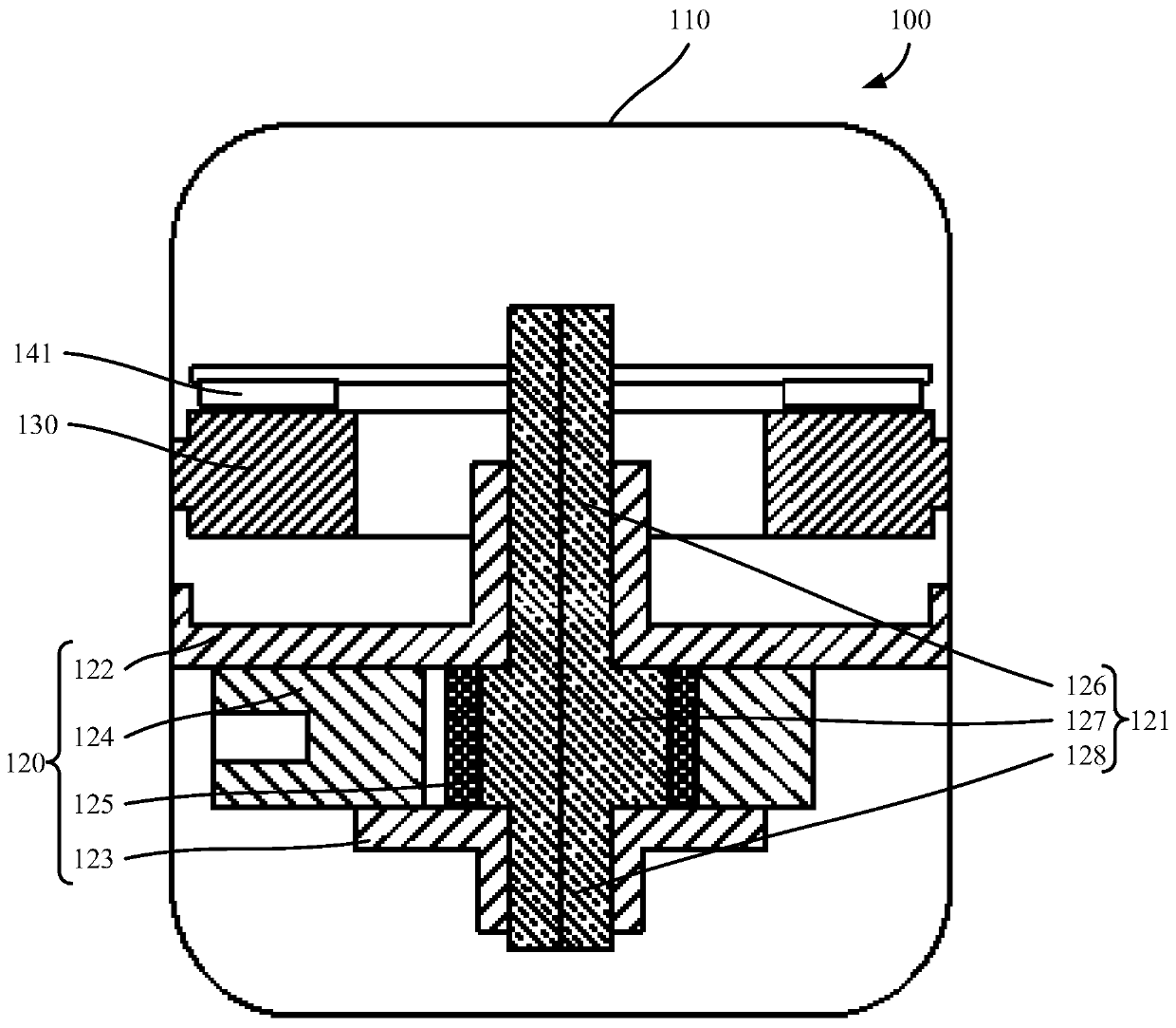
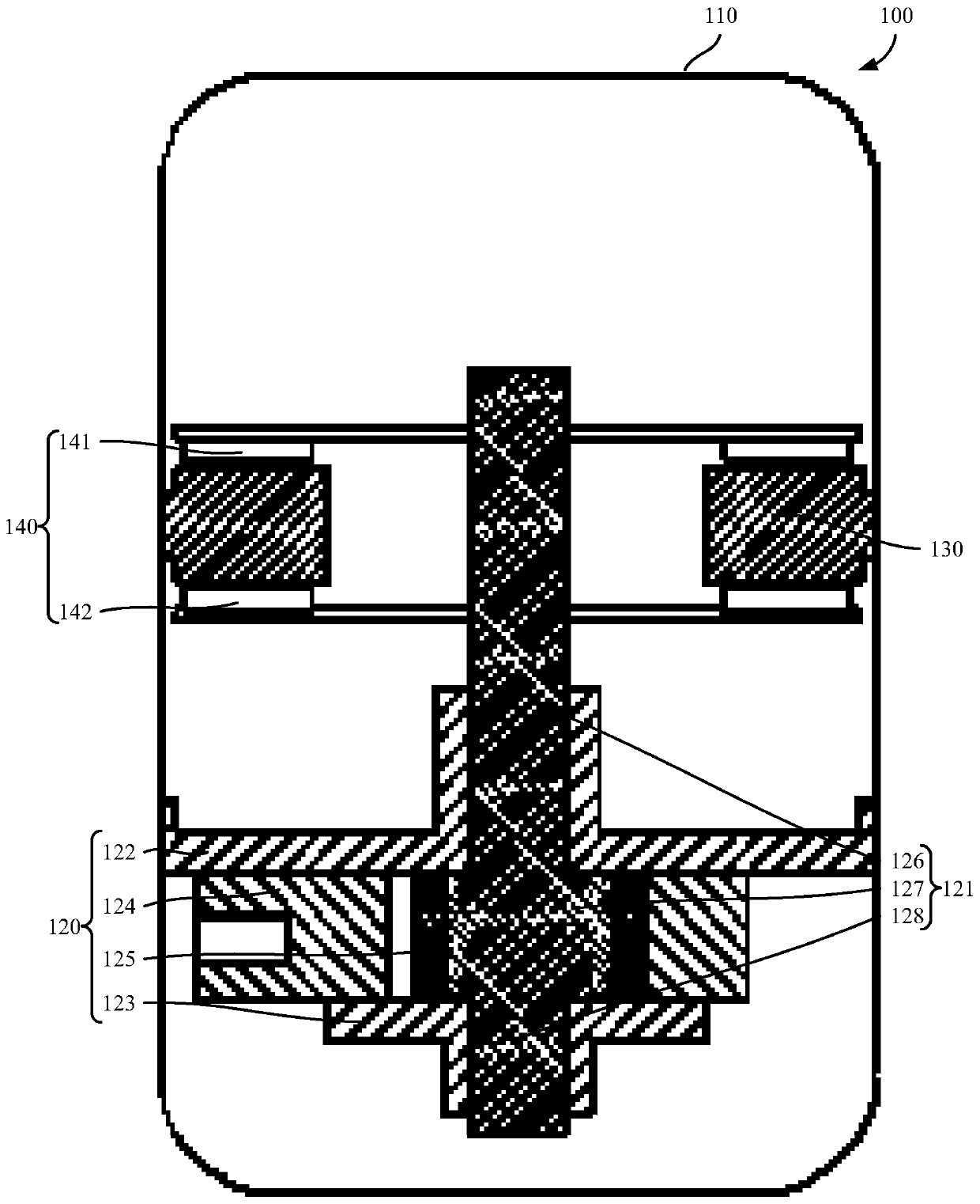
[0050] Such as Figure 2 to Figure 5 As shown, according to the first aspect of the present invention, the present invention provides a compressor 100, the compressor 100 includes a casing 110, a pump body assembly 120 and a motor assembly, wherein the motor assembly includes a stator assembly 130 and a rotor assembly 140 .
[0051] The compressor 100 provided by the present invention includes a casing 110, a pump body assembly 120 and a motor assembly, wherein the motor assembly includes a stator assembly 130 and a rotor assembly 140, the rotor assembly 140 is connected to the pump body assembly 120, and the rotor assembly 140 can drive the pump The body assembly 120 performs rotational compression, and the rotor assembly 140 is arranged in the axial direction of the stator assembly 130, that is, the rotor assembly 140 is distributed on one or both sides of the axial direction of the stator assembly 130, and the stator assembly 130 drives the rotor The assembly 140 rotates, ...
Embodiment 2
[0054] On the basis of embodiment one, further, as figure 2 As shown, the rotor assembly 140 includes: a first rotor disk 141 disposed on either side of the stator assembly 130 in the axial direction, and the first rotor disk 141 is connected with the pump body assembly 120 .
[0055] In this embodiment, the rotor assembly 140 includes a first rotor disk 141, and the first rotor disk 141 is connected with the pump body assembly 120, so that the first rotor disk 141 can directly drive the pump body assembly 120 to rotate and compress, since only one The first rotor disk 141 makes the compressor 100 simple in structure and low in production cost.
Embodiment 3
[0057] On the basis of embodiment one, further, as Figure 3 to Figure 5 As shown, the rotor assembly 140 includes: a first rotor disk 141 disposed on one side in the axial direction of the stator assembly 130; a second rotor disk 142 disposed on the other side of the stator assembly 130 in the axial direction; The bracket connects the first rotor disk 141 and the second rotor disk 142 , the rotor bracket is connected with the pump body assembly 120 , or the first rotor disk 141 and the second rotor disk 142 are respectively connected with the pump body assembly 120 .
[0058] In this embodiment, the rotor assembly 140 includes a first rotor disk 141, a second rotor disk 142 and a rotor bracket, wherein the first rotor disk 141 is arranged on one side in the axial direction of the stator assembly 130, and the second rotor disk 142 142 is arranged on the other side of the stator assembly 130 in the axial direction, by setting the first rotor disk 141 and the second rotor disk 1...
PUM
 Abstract
Description
Claims
Application Information
 - R&D
- Intellectual Property
- Life Sciences
- Materials
- Tech Scout
- Unparalleled Data Quality
- Higher Quality Content
- 60% Fewer Hallucinations
Browse by: Latest US Patents, China's latest patents, Technical Efficacy Thesaurus, Application Domain, Technology Topic, Popular Technical Reports.
© 2025 PatSnap. All rights reserved.Legal|Privacy policy|Modern Slavery Act Transparency Statement|Sitemap|About US| Contact US: help@patsnap.com


