Supercharge Your Innovation With Domain-Expert AI Agents!

Engagement and disengagement device of rotary kiln

A technology of clutch device and rotary kiln, which is applied in clutches, mechanically driven clutches, and clutches that mesh with each other, can solve the problems of power consumption, safety, time consumption, and time consumption, so as to improve efficiency, save time, and avoid Difficult and Dangerous Effects

Inactive Publication Date: 2020-06-02
JIANGSU PENGFEI GROUP
View PDF7 Cites 0 Cited by
  • Summary
  • Abstract
  • Description
  • Claims
  • Application Information

AI Technical Summary

Problems solved by technology

When the rotary kiln stops suddenly, that is, when the main transmission system fails, it is necessary to manually pull the clutch handle to make the clutch fit and engage the power transmission. Only by turning the toothed coupling can it be engaged. At this time, it is required to turn the auxiliary reducer or remove the auxiliary motor casing and turn the motor to rotate the toothed coupling, which is time-consuming and labor-intensive.
[0006] 2. When the rotary kiln is driven by the auxiliary transmission device to the main transmission system, it is necessary to disconnect the clutch between the rotary kiln and the auxiliary transmission device. Due to the biased distribution of materials in the rotary kiln, the load on the clutch may be large, resulting in The difficulty of manual wrenching increases
[0007] 3. If the clutch between the rotary kiln and the auxiliary transmission cannot be disconnected smoothly, it will be very difficult to start the main transmission system (main transmission motor)
[0008] To sum up, when the auxiliary transmission device in the prior art adopts the helical gear clutch to engage and separate from the rotary kiln, it is time-consuming, labor-intensive and not safe, and cannot provide favorable and reliable power transmission and disconnection for the auxiliary transmission device. Guarantee
[0009] Therefore, there is an urgent need for a rotary kiln clutch device that solves the problems of time-consuming, labor-intensive and low safety when the auxiliary transmission device is engaged and separated from the rotary kiln by using a helical gear clutch. Provide favorable and reliable guarantee

Method used


Image

  • Engagement and disengagement device of rotary kiln
  • Engagement and disengagement device of rotary kiln
  • Engagement and disengagement device of rotary kiln

Examples


Embodiment Construction

[0057] In order to make the object, technical solution and advantages of the present invention clearer, the implementation manner of the present invention will be further described in detail below in conjunction with the accompanying drawings.

[0058] The terms "first", "second", etc. used herein do not specifically refer to a sequence or order, nor are they used to limit the present application, but are only used to distinguish components or operations described with the same technical terms. .

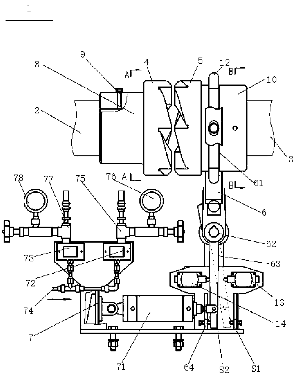
[0059] In one embodiment of the present invention, figure 1 It is a schematic front view of a rotary kiln clutch device according to an embodiment of the present invention. Such as figure 1 As shown, the rotary kiln clutch device 1 is used for the connection between the input shaft 2 of the main reducer on the rotary kiln equipment and the output shaft 3 of the auxiliary reducer of the rotary kiln. The rotary kiln clutch device 1 includes the first part 4 of the helical gear clutc...


PUM


Abstract

The invention relates to an engagement and disengagement device of a rotary kiln. The engagement and disengagement device comprises a helical tooth clutch first portion, a helical tooth clutch secondportion, a connecting portion and a drive system. The helical tooth clutch first portion is connected with an input shaft of a main speed reducer. The helical tooth clutch second portion is connectedwith an output shaft of an auxiliary speed reducer and opposite to the helical tooth clutch first portion and can move towards the helical tooth clutch first portion and away from the helical tooth clutch first portion. The connecting portion is fixedly connected with the helical tooth clutch second portion and used for driving the helical tooth clutch second portion to move towards and away fromthe helical tooth clutch first portion, when the connecting portion is set at a first position, the helical tooth clutch second portion is driven to be engaged with the helical tooth clutch first portion, and when the connecting portion is set at a second position, the helical tooth clutch second portion is driven to be separated from the helical tooth clutch first portion. The drive system is connected with the connecting portion. The function that the output shaft of the auxiliary speed reducer and the input shaft of the main speed reducer are automatically switched on within a first time after failure, outage and kiln stop can be achieved, manual operation is not needed, and the rotary kiln can recover to rotate at the first time.

Description

technical field [0001] The invention relates to the technical field of transmission devices, in particular to a clutch device for a rotary kiln. Background technique [0002] Rotary kiln, also known as rotary kiln, is a cylindrical object with a certain slope, the slope is 3-3.5%. The rotation of the kiln is used to promote the mixing of materials in the rotary kiln (rotary kiln), so that the materials are mixed with each other, contact to react. [0003] The rotary kiln usually includes a main transmission system and an auxiliary transmission device. When the main transmission system is working normally, the rotary kiln is driven to rotate by the main transmission system. The main transmission system adopts a single transmission, and a main transmission motor drives the rotary kiln to rotate. If the main drive system fails, the rotary kiln will use the auxiliary drive to drive the rotation. [0004] In the process of realizing the present invention, the inventor finds tha...

Claims


Application Information

Patent Timeline
IPC IPC(8): F16D11/14F16D11/00F16D121/02F16D125/02F16D125/04
CPCF16D11/14F16D2011/008F16D2121/02F16D2125/02F16D2125/04
Inventor 丁浩韩楷丁同华王泽
Owner JIANGSU PENGFEI GROUP
Features
  • R&D
  • Intellectual Property
  • Life Sciences
  • Materials
  • Tech Scout
  • Unparalleled Data Quality
  • Higher Quality Content
  • 60% Fewer Hallucinations
Learn More