Optical detection device and optical detection method for coaxiality machining errors of shaft hole

A processing error and optical detection technology, which is applied in the direction of using optical devices, measuring devices, instruments, etc., can solve the problems affecting the detection accuracy, the limitation of processing equipment selection, the complex structure of the four-way, etc., and achieve the effect of high detection accuracy

Active Publication Date: 2020-06-02
CHANGCHUN INST OF OPTICS FINE MECHANICS & PHYSICS CHINESE ACAD OF SCI
View PDF6 Cites 3 Cited by
  • Summary
  • Abstract
  • Description
  • Claims
  • Application Information

AI Technical Summary

Problems solved by technology

[0007] (3) The four-way structure is complex and the span is large, and it is difficult to detect the coaxiality error of the shaft ends on both sides. At present, the control of the machining error is usually realized through the positioning of the CNC machine tool itself, and the CNC machine tool itself belongs to a dynamic coordinate system, and there are multiple This will affect the detection accuracy due to the introduction of its own error in the detection, and the accuracy of the CNC machine tool itself increases linearly with the increase of the range of motion
However, with the continuous increase of the scale of structural parts, the choice of processing equipment will be greatly restricted

Method used


Image

  • Optical detection device and optical detection method for coaxiality machining errors of shaft hole
  • Optical detection device and optical detection method for coaxiality machining errors of shaft hole
  • Optical detection device and optical detection method for coaxiality machining errors of shaft hole

Examples


Embodiment Construction

[0054] The following will clearly and completely describe the technical solutions in the embodiments of the present invention with reference to the accompanying drawings in the embodiments of the present invention. Obviously, the described embodiments are only part of the embodiments of the present invention, not all of them. Based on the embodiments of the present invention, all other embodiments obtained by persons of ordinary skill in the art without creative efforts fall within the protection scope of the present invention.

[0055] It should be noted that if there is a directional indication (such as up, down, left, right, front, back...) in the embodiment of the present invention, the directional indication is only used to explain the position in a certain posture (as shown in the accompanying drawing). If the specific posture changes, the directional indication will also change accordingly.

[0056] In addition, if there are descriptions involving "first", "second" and ...


PUM


Abstract

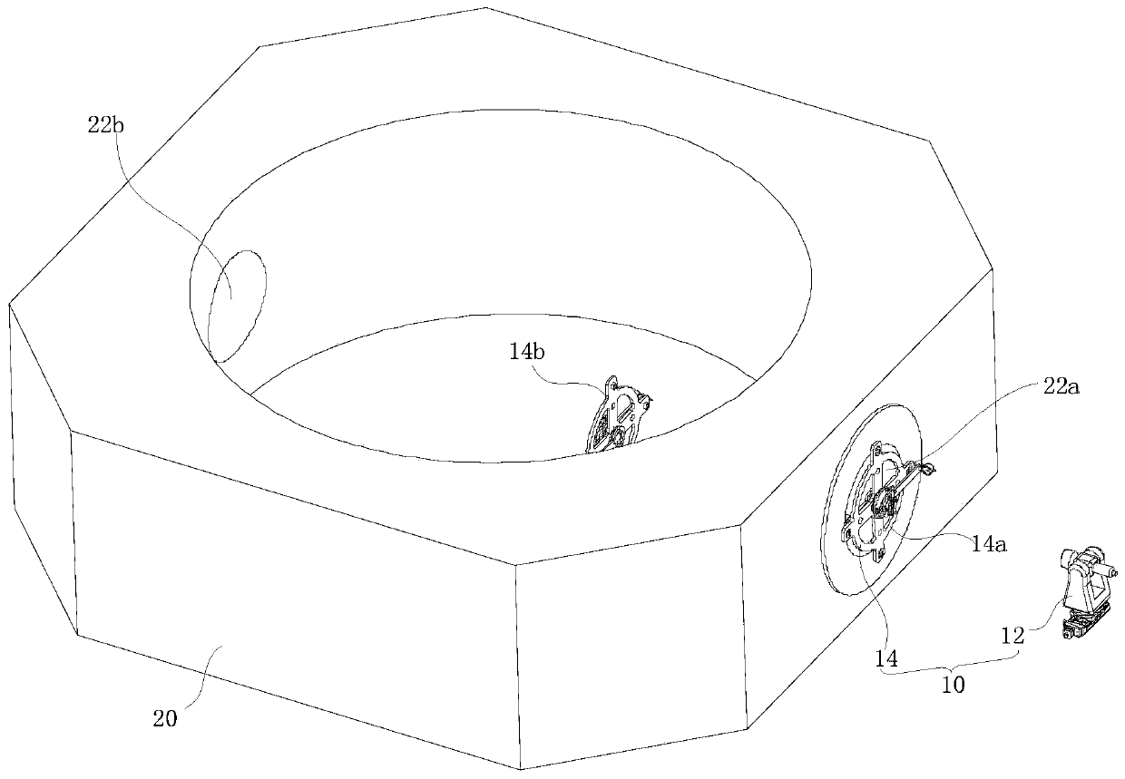
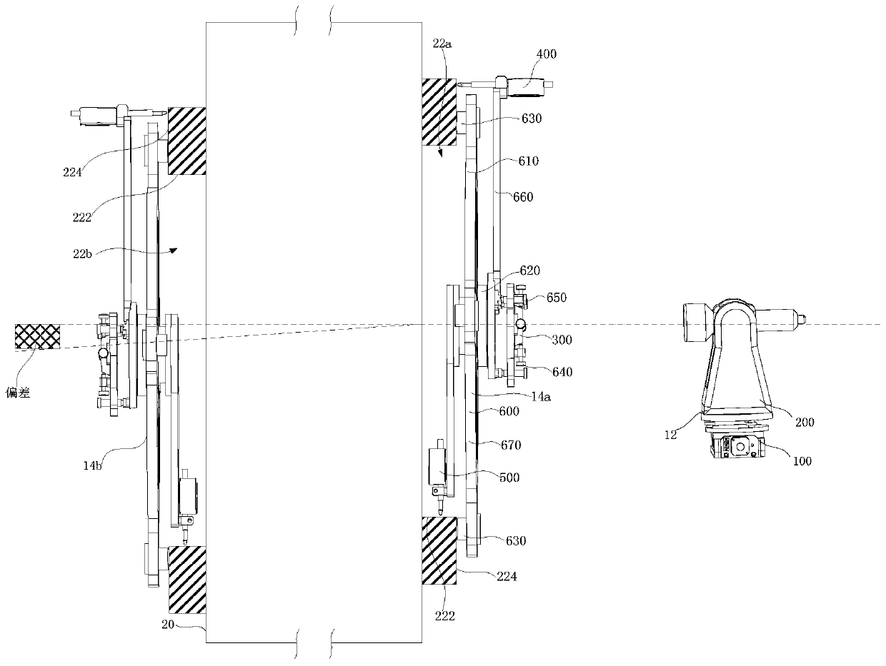
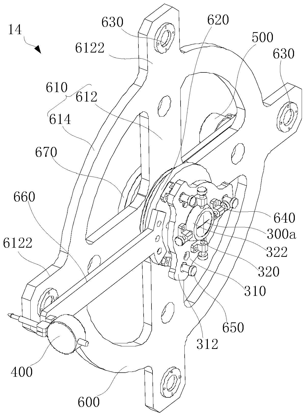
The invention discloses an optical detection device and an optical detection method for coaxiality machining errors of a shaft hole. The optical detection device comprises a main optical assembly andtwo auxiliary optical assemblies. The main optical assembly comprises a two-dimensional adjusting platform and a total station. Each auxiliary optical assembly comprises a plate lens, a first dial indicator, a second dial indicator and a five-dimensional adjusting frame. Each five-dimensional adjusting frame comprises an adjusting frame base, a pivotal bearing, a first adjusting mechanism, a second adjusting mechanism and a third adjusting mechanism, wherein the pivotal bearing is rotationally connected with the adjusting frame base, and is used for driving the flat lens, the first dial indicator and the second dial indicator to rotate; the first adjusting mechanism is used for adjusting the position and inclination of the adjusting frame base; the second adjusting mechanism and the thirdadjusting mechanism are used for adjusting the inclination and position of the flat lens; the flat lens is provided with an auxiliary cross wire; the first dial indicator is used for measuring the vertical deviation between the shaft end surface and the axis of the pivotal bearing; and the second dial indicator is used for measuring the deviation between the shaft hole surface and the center of the pivotal bearing. The optical detection device and the optical detection method have high detection precision.

Description

technical field [0001] The invention relates to the technical field of coaxiality processing error detection, in particular to an optical detection device and an optical detection method for the coaxiality processing error of a shaft hole. Background technique [0002] The development of astronomical telescopes is a successful feat for human beings to conquer the universe and explore the mysteries of the universe. As astronomy needs to study faint targets, such as the formation and evolution of stars in the deep space of the universe, the distribution and structure of galaxies, solar physics, time-domain astronomy, galaxy physics, and extrasolar planet physics, etc., the ground-based large-scale optical telescopes have been promoted to large-aperture , high-resolution direction, the reason is that in the universe, apart from specific particles (cosmic rays, neutrinos, etc.), the only carrier of information is the electromagnetic radiation that can be received on or near the ...

Claims


Application Information

Patent Timeline
IPC IPC(8): G01B11/27
CPCG01B11/27
Inventor 曹玉岩王建立李洪文王志臣周超王洪浩
Owner CHANGCHUN INST OF OPTICS FINE MECHANICS & PHYSICS CHINESE ACAD OF SCI
Why Eureka
Try Eureka