Positioning method and system for target area seismic source containing unknown cavity

A technology for target area and source location, applied in seismology, seismic signal processing, measurement devices, etc., can solve problems such as narrow application range, and achieve the effect of wide application prospect, wide application range and simple operation

Active Publication Date: 2020-06-02
CENT SOUTH UNIV
View PDF12 Cites 4 Cited by
  • Summary
  • Abstract
  • Description
  • Claims
  • Application Information

AI Technical Summary

Problems solved by technology

However, in the actual engineering environment, it is impossible for us to fully understand the position, size, and shape of all the cavities in each area to be located, so the existing seismic source location methods have a narrow range of application

Method used


Image

  • Positioning method and system for target area seismic source containing unknown cavity
  • Positioning method and system for target area seismic source containing unknown cavity
  • Positioning method and system for target area seismic source containing unknown cavity

Examples


Embodiment 1

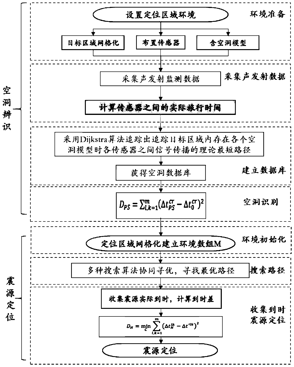
[0047] This embodiment discloses a seismic source location method with an unknown cavity location, including the following steps:

[0048] Step 1. Identify the position of the cavity; specifically, the following steps are included:

[0049] On-site data collection: arrange m acoustic emission sensors at different positions in the target area, and collect the actual travel time of signals between each acoustic emission sensor on site; where m is an integer greater than or equal to 4;

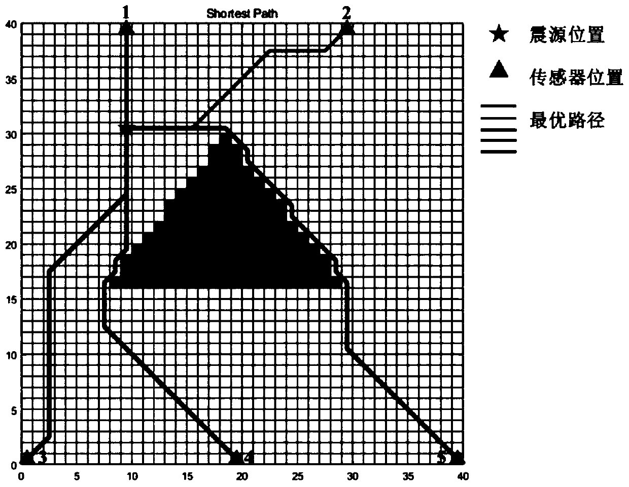
[0050] Simulation analysis: construct multiple cavity models with different positions, sizes, and shapes for the target area; for each cavity model, track the shortest path of signal propagation between the acoustic emission sensors when the cavity model exists in the target area, so as to obtain the Theoretical travel time of signals between AE sensors;

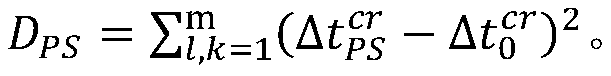
[0051] Cavity position identification: calculate the deviation between the theoretical travel time and the actual travel time of the signals ...

Embodiment 2

[0055] In this embodiment, on the basis of Embodiment 1, the acoustic emission sensors all have the function of transmitting pulse signals.

Embodiment 3

[0057] This embodiment is based on Embodiment 2. In the step 1, set the active seismic source, that is, the acoustic emission sensor that emits the pulse signal as S c , the time of its pulse signal emission is The rth acoustic emission sensor S r Received S c The actual time of the transmitted pulse signal is Then the acoustic emission sensor S c with acoustic emission sensor S r The actual travel time of the signal between is:


PUM


Abstract

The invention discloses a positioning method and system for target area seismic source containing unknown cavity, and the method comprises the following steps: 1, recognizing the position of the cavity, specifically comprising the steps of arranging a plurality of sensors at different positions of the target area, and collecting the actual travel time of signals among the sensors; constructing a plurality of cavity models for the target area; for each cavity model, tracking the shortest path of signal propagation among the sensors when the cavity model exists in the target area so as to obtaintheoretical travel time of signals among the sensors; respectively calculating the deviation between the theoretical travel time and the actual travel time of the signals between the sensors corresponding to each cavity model, wherein the position of the cavity model corresponding to the minimum deviation is the cavity position in the identified target area; and step 2, on the basis of the identified cavity position, carrying out seismic source positioning on the target area. The method can achieve the precise positioning of the seismic source under the condition that the position of the cavity is unknown.

Description

technical field [0001] The invention relates to a seismic source positioning method and system in a target area containing unknown cavities, and belongs to the technical fields of non-destructive testing and safety monitoring. Background technique [0002] With the mining of deep mineral resources and the development and utilization of underground space, underground projects continue to go deep, especially in metal mines and tunnel projects, and rockburst accidents have increased dramatically. In order to reduce casualties and property losses caused by rockburst disasters, microseismic technology developed based on geophysics can effectively monitor the location of rock microfractures. In recent years, it has been widely used in mine safety, hydropower underground engineering monitoring, especially in the monitoring of faults and rock micro-fracture signals in tunnels and mining engineering, and has played an important role, providing a scientific basis for evaluating rockbu...

Claims


Application Information

Patent Timeline
Patent Type & Authority Applications(China)
IPC IPC(8): G01V1/28G01V1/30
CPCG01V1/282G01V1/30
Inventor 董陇军陶晴
Owner CENT SOUTH UNIV
Why Eureka
Try Eureka