Common-mode voltage control method for doubly-fed motor converter system

A converter system, common mode voltage technology, applied in the generator control circuit, control system, control generator, etc., can solve the problems of rotor slip ring and rotor bearing failure, etc.

Active Publication Date: 2020-06-02
苏州乾能电气有限公司
View PDF7 Cites 0 Cited by
  • Summary
  • Abstract
  • Description
  • Claims
  • Application Information

AI Technical Summary

Problems solved by technology

However, the generator rotor winding is connected to the converter through slip rings, and the rotor slip rings and rotor bearings often fail

Method used


Image

  • Common-mode voltage control method for doubly-fed motor converter system
  • Common-mode voltage control method for doubly-fed motor converter system
  • Common-mode voltage control method for doubly-fed motor converter system

Examples


Embodiment Construction

[0049] The present invention will be described in further detail below in conjunction with the accompanying drawings, but it is not intended to limit the protection scope of the present invention.

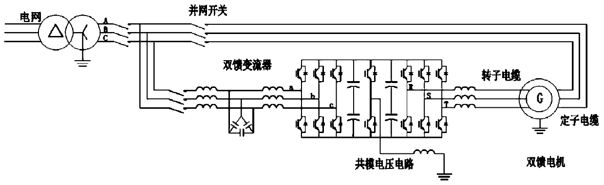
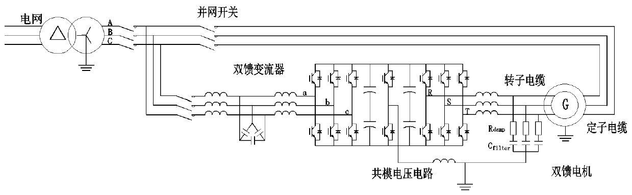
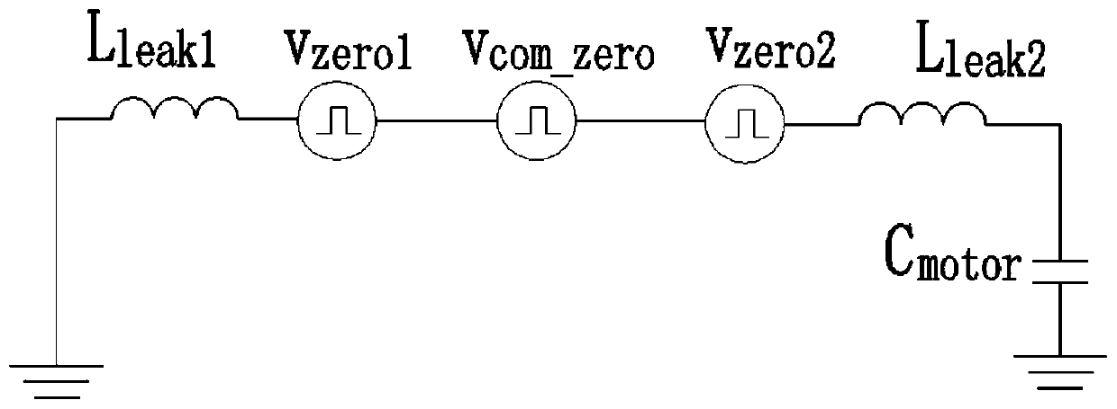
[0050] Such as Figure 1-4 As shown, 1. A doubly-fed generator converter common-mode voltage control method, a common-mode voltage generation circuit is added to the doubly-fed generator and converter circuit, the generation circuit adopts a bridge arm, connected to the DC On the bus; the control signal of the common-mode voltage injected into the bridge arm is the sum of the SPWM signals on the grid side divided by 3, and the sum of the SVPWM signals on the motor side divided by 3:

[0051]

[0052] That is: v com_zero2 (t)=v zero1 (t)+v zero2 (t),

[0053] Ideally: v zero1 (t)+v com_zero2 (t)+v zero2 (t) = 0;

[0054] Among them, the SPWM signal on the grid side is as follows: The SVPWM signal on the motor side is as follows:

[0055] The common-mode voltage injec...


PUM


Abstract

The invention belongs to the field of electric appliance circuits, and particularly relates to a common-mode voltage control method for a doubly-fed motor converter. According to the method, a common-mode voltage generation circuit is added on a doubly-fed generator and a converter circuit. The generation circuit adopts a bridge arm and is connected to a direct current bus; a control signal of thecommon-mode voltage injection bridge arm is obtained by adding one third of the sum of SVPWM signals at the power grid side and one third of the sum of SVPWM signals at the motor side, the formula isshown in the description, that is, Vcom_zero2(t)=-Vzero1(t)-Vzero2(t), and in an ideal condition, Vzero1(t)+Vcom_zero2(t)+Vzero2(t)=0. Compared with a traditional common-mode voltage generation circuit, the common-mode voltage generation circuit is small in power and low in cost, and low-frequency common-mode signals vzero1 and vzero2 can be restrained, so that insulation of a motor winding is facilitated, and electric leakage of a rotor bearing and a slip ring is prevented.

Description

technical field [0001] The invention belongs to the field of electrical circuits, and in particular relates to a common-mode voltage control method of a doubly-fed motor converter system. Background technique [0002] Doubly-fed generator and converter system is the most widely used solution for wind turbines. Since the converter of the doubly-fed system is connected to the rotor side, the power of the converter is only between 1 / 3 and 1 / 4 of the power of the motor, and the cost of the converter is low, the loss is small, and the efficiency is high. However, the generator rotor winding is connected to the converter through slip rings, and the rotor slip rings and rotor bearings often fail. The main cause of insulation damage is the sudden change of rotor voltage dv / dt, including differential mode voltage and common mode voltage. The differential mode voltage is usually adjusted by methods such as filters and IGBT switching speed. [0003] Common-mode voltage solutions, so...

Claims


Application Information

Patent Timeline
Patent Type & Authority Applications(China)
IPC IPC(8): H02P9/00H02M5/458H02M1/12H02P101/15
CPCH02P9/007H02P9/006H02M5/4585H02M1/12H02P2101/15H02M1/123Y02E10/76
Inventor 任晓峰王晓坤
Owner 苏州乾能电气有限公司
Why Eureka
Try Eureka