Network compensation controller heat dissipation device

A network compensation and heat dissipation device technology, applied in chemical instruments and methods, cooling/ventilation/heating transformation, electrical components, etc., can solve the problems of radiator overheating, single heat dissipation effect, and poor heat dissipation of the controller, etc. Achieve the effect of improving heat dissipation, good heat dissipation effect, and convenient control

Active Publication Date: 2020-06-02
QUFU NORMAL UNIV
View PDF2 Cites 3 Cited by
  • Summary
  • Abstract
  • Description
  • Claims
  • Application Information

AI Technical Summary

Problems solved by technology

The device uses the rotation of the fan to generate an upward airflow. The airflow flows to the network controller through the ventilation slot. The hot airflow transfers heat to several heat conducting plates. To improve the efficiency of heat conduction, the axial flow fan located on the right side of the box blows the airflow to the left side, while the condensing device cools the air, and the heat on the heat conduction plate is taken away by the cold airflow, and the airflow passes through the cooling slot on the left side of the box body Through a series of heat dissipation, the heat dissipation is fast and efficient, which keeps the temperature of the network controller at room temperature, ensures that the network controller can continue to work efficiently and stably, and prolongs its service life, but the heat dissipation effect of the device is relatively simple , it may cause that some parts of the controller do not perform good heat dissipation, resulting in local overheating of the radiator, so the device needs to be improved

Method used


Image

  • Network compensation controller heat dissipation device
  • Network compensation controller heat dissipation device
  • Network compensation controller heat dissipation device

Examples


Embodiment 1

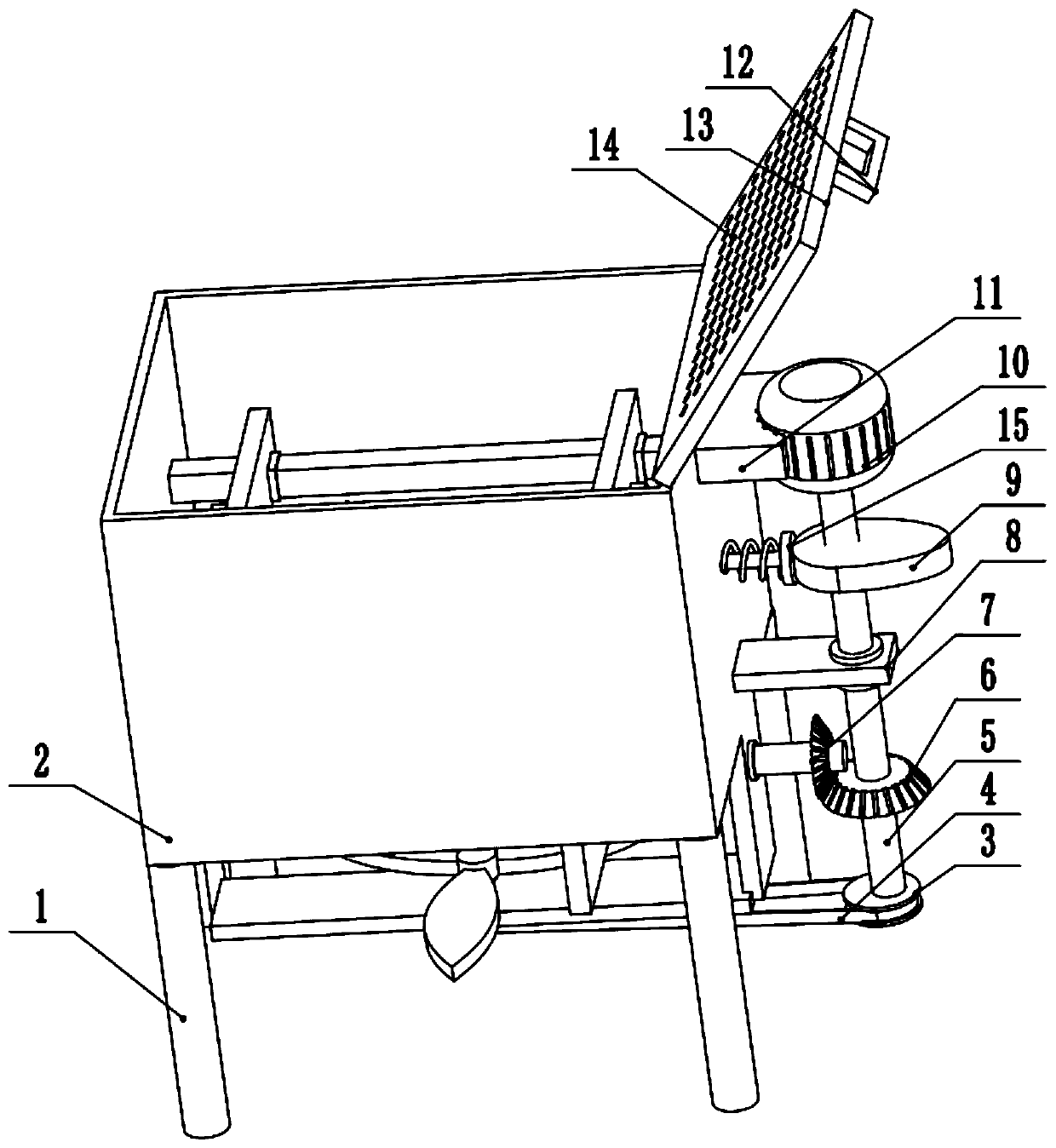
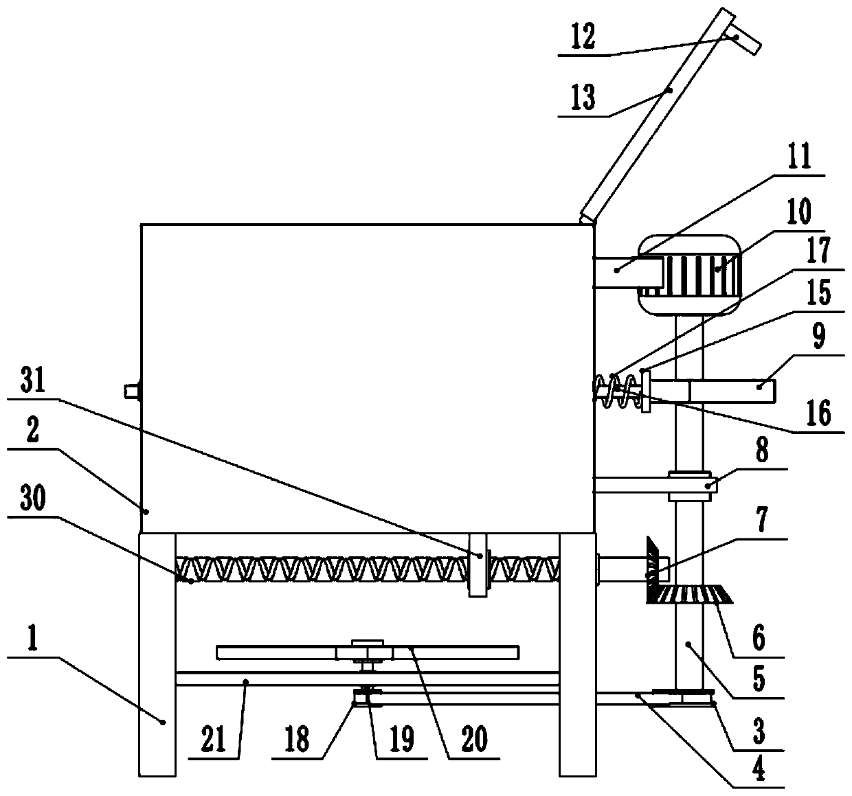
[0028] see Figure 1-4 , a network compensation controller cooling device, including a box 2, the lower surface of the box 2 left and right sides are provided with table legs 1, the bottom of the box 2 is provided with an air inlet 22, the top of the box 2 rotates on the right Connect the baffle plate 13, the middle part of the baffle plate 13 is provided with an air vent 14, the end of the baffle plate 13 is provided with a handle 12, the upper part of the right side wall of the box body 2 is provided with a driving motor 10, and the right side wall of the box body 2 The top is provided with a motor holder 11, the right side of the motor holder 11 is fixedly connected to the drive motor 10, the output shaft of the drive motor 10 is fixedly connected to the upper end of the rotating shaft 5, the right side wall bottom of the box body 2 is provided with a fixed plate 8, the fixed plate The right side of 8 rotates and connects the middle part of rotating shaft 5, and the top of ...

Embodiment 2

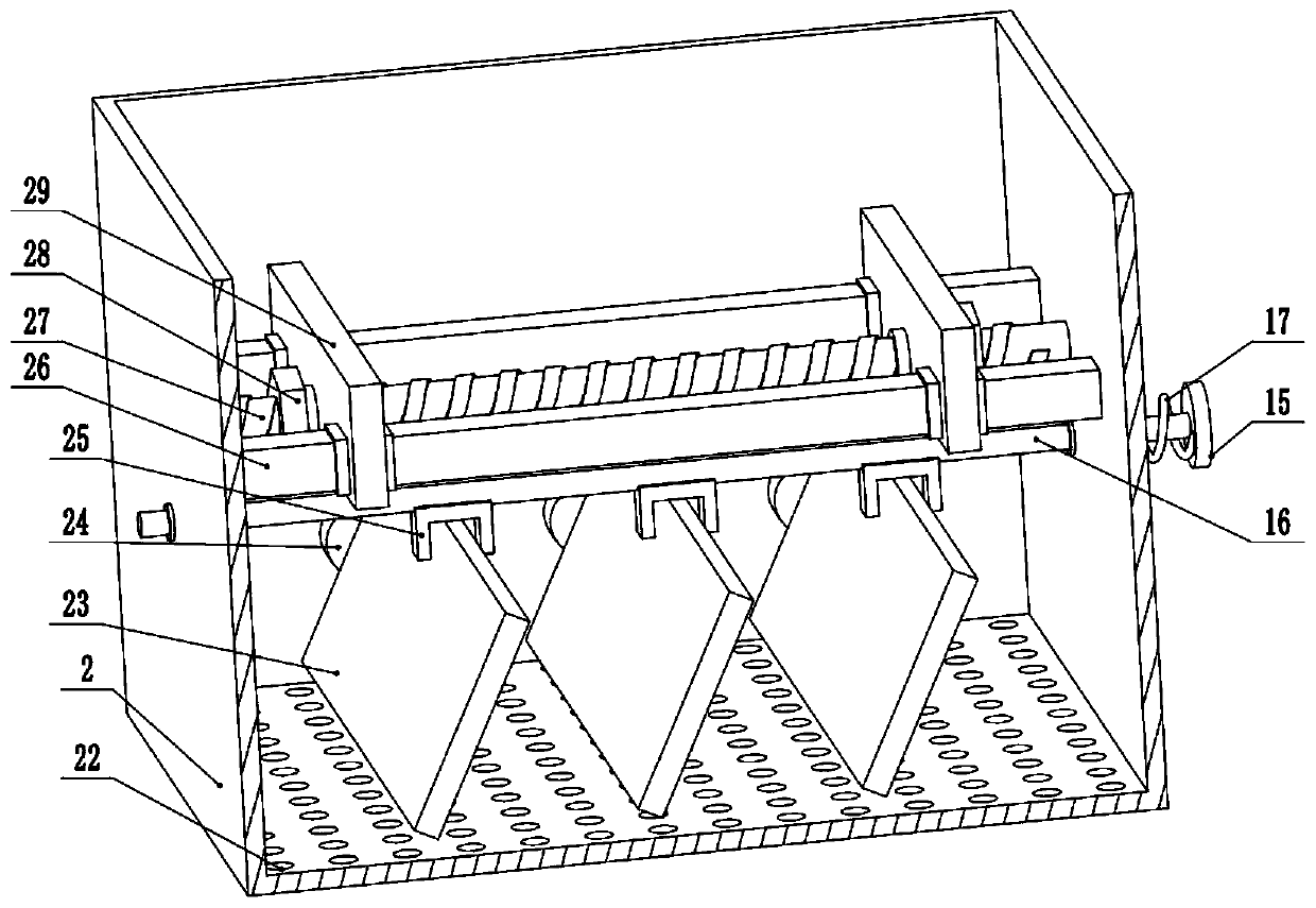
[0031] see image 3 and Figure 4 , the other content of this embodiment is the same as Embodiment 1, the difference is that: the left and right sides of the support rod 26 are slidably connected to the clamping plate 29, the top of the box body 2 is provided with a first screw rod 27, the first wire The left and right sides of the rod 27 run through and connect the lower part of the clamping plate 29 , and the left and right ends of the first screw rod 27 are provided with fastening nuts 28 . When the device is in normal use, the controller can be directly placed on the support rod 26. At this time, the controller is in a suspended state, so as to better dissipate heat. However, due to the different models of the controllers, the sizes of the controllers are different, so In the future, the controller can be better fixed in this device, and the clamping plate 29 is set on the upper part of the device, and the first screw rod 27 and the fastening nut 28 are used to fix the cl...


PUM


Abstract

The invention relates to the technical field of network communication accessories, and discloses a network compensation controller heat dissipation device. The device comprises a box body, wherein thebottom of the box body is provided with an air inlet; a baffle is rotationally connected to the right side of the top end of the box body; an air hole is formed in the middle of the baffle; a handleis arranged at the end part of the baffle; a driving motor is arranged at the upper part of the right side wall of the box body; an output shaft of the driving motor is fixedly connected with the upper end of a rotating shaft; a cam is arranged on the upper part of the rotating shaft; the lower part of the rotating shaft is provided with a first bevel gear; the first bevel gear is arranged on andmeshed with a second bevel gear; the second bevel gear is fixedly connected with the right side of a second lead screw; the middle of the second lead screw is in threaded connection with the middle ofa scraper; and a first belt wheel is arranged at the lower end of the rotating shaft. According to the network compensation controller heat dissipation device, a flow guide plate can uninterruptedlyswing left and right by arranging the cam and a push plate, so that air flow in the box body can swing left and right, effective heat dissipation is conducted on the exterior of the controller, and the heat dissipation effect is improved.

Description

technical field [0001] The invention relates to the technical field of network communication accessories, in particular to a cooling device for a network compensation controller. Background technique [0002] The automatic control based on the principle of invariance is called compensation control, which realizes the compensation of the system for all or part of the disturbance. According to the difference of its structure, the compensation control system generally has two kinds of feed-forward control system and large delay process system. Compensation control systems are widely used in industrial production processes, medicine, psychology, military, electrical machinery, computers and other fields. [0003] Feedforward control is a control method based on the principle of invariance, and it belongs to an open-loop control system. Commonly used feedforward control systems include simple feedforward control systems, feedforward-feedback control systems, and feedforward-cas...

Claims


Application Information

Patent Timeline
Patent Type & Authority Applications(China)
IPC IPC(8): H05K7/20B08B1/00
CPCH05K7/20145H05K7/20172B08B1/005
Inventor 魏云亮李圆圆
Owner QUFU NORMAL UNIV
Why Eureka
Try Eureka