Hauling structure and hauling frame device thereof

A technology for a backrest and a seat cushion is applied in the field of traction structures and their traction frame devices, and can solve problems such as affecting the traction effect and incapable of patient traction.

Inactive Publication Date: 2020-06-05
THE FIRST AFFILIATED HOSPITAL OF ARMY MEDICAL UNIV
View PDF8 Cites 4 Cited by
  • Summary
  • Abstract
  • Description
  • Claims
  • Application Information

AI Technical Summary

Problems solved by technology

[0004] The purpose of the present invention is to provide a traction structure, aiming to solve the waist traction in the prior art, which is to draw the patient's waist towards the legs with the crotch as the axis, or draw the patient towards the left and right sides with the crotch as the axis, so The technical problem that the patient cannot be tractioned in an oblique orientation, which affects the traction effect

Method used


Image

  • Hauling structure and hauling frame device thereof
  • Hauling structure and hauling frame device thereof
  • Hauling structure and hauling frame device thereof

Examples


no. 1 example

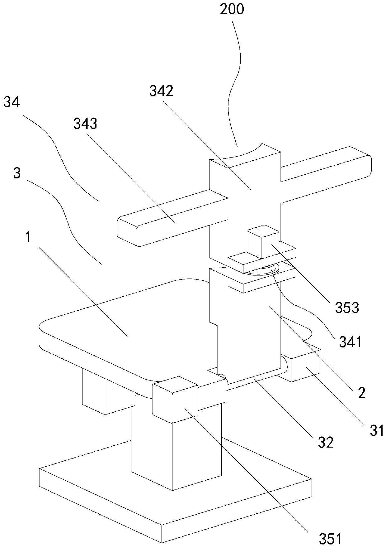
[0027] see Figure 1 to Figure 3, the present invention provides a traction structure 200, including a seat cushion 1, a first backrest 2 and a waist adjustment assembly 3; In the direction away from the seat cushion 1, the waist adjustment assembly 3 is fixedly connected with the first backrest 2, and is rotatably connected with the seat cushion 1, and drives the first backrest 2 and the seat cushion 1 to rotate; The waist adjusting assembly 3 includes a fixed base 31, a rotating support rod 32, a waist fixing member 33, a lateral traction member 34 and a driving member 35, the fixed base 31 is fixedly connected with the seat cushion 1, and is located close to the seat cushion 1. On one side of the first backrest 2 , the rotating support rod 32 is fixedly connected with the first backrest 2 and rotatably connected with the fixed base 31 , and is located near the seat cushion 1 on the first backrest 2 On one side, the waist fixing member 33 is fixedly connected with the first...

no. 2 example

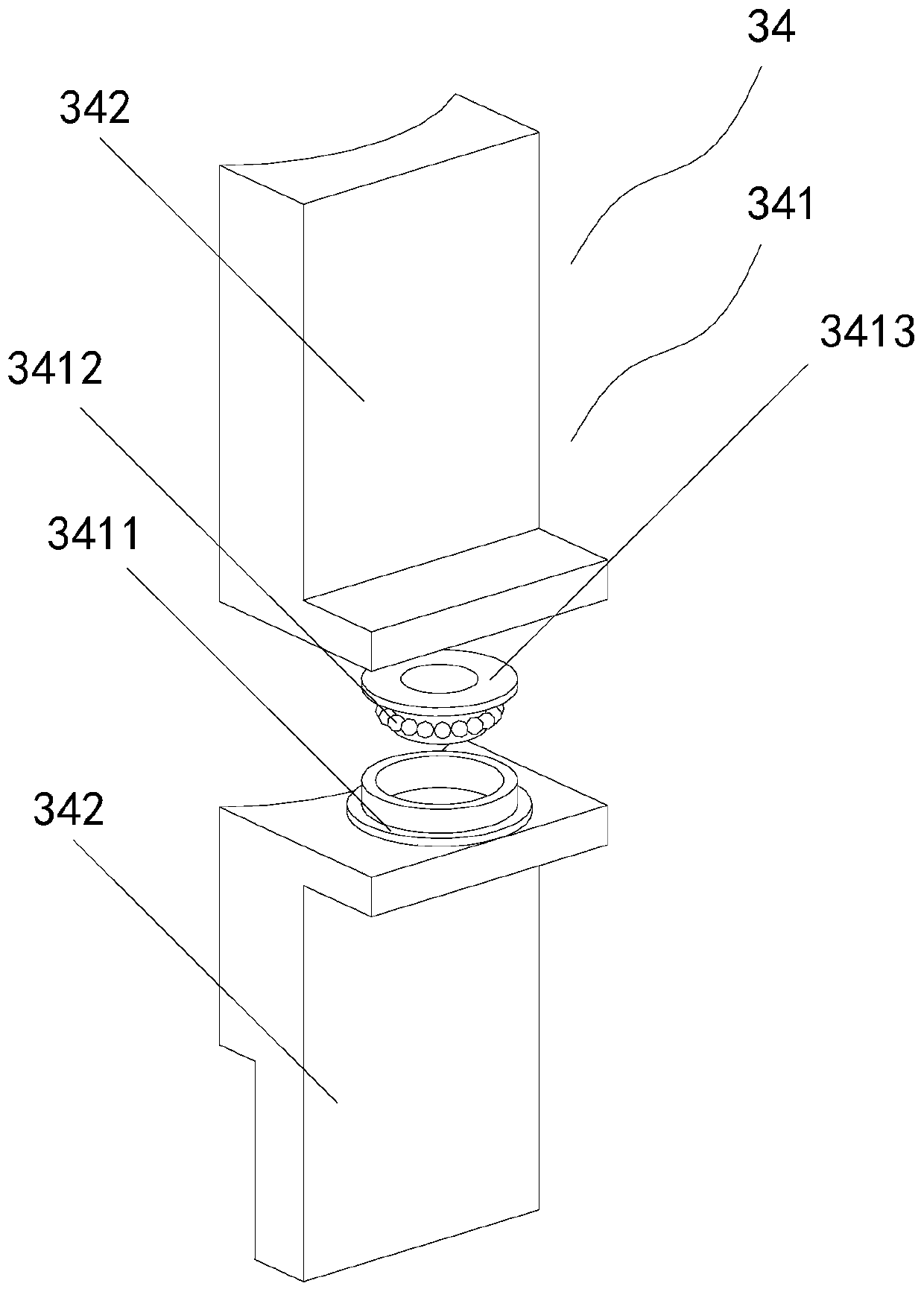
[0032] see Figure 1 to Figure 5 , the present invention provides a traction structure 200, including a seat cushion 1, a first backrest 2 and a waist adjustment assembly 3; In the direction away from the seat cushion 1, the waist adjustment assembly 3 is fixedly connected with the first backrest 2, and is rotatably connected with the seat cushion 1, and drives the first backrest 2 and the seat cushion 1 to rotate; The waist adjusting assembly 3 includes a fixed base 31, a rotating support rod 32, a waist fixing member 33, a lateral traction member 34 and a driving member 35, the fixed base 31 is fixedly connected with the seat cushion 1, and is located close to the seat cushion 1. On one side of the first backrest 2 , the rotating support rod 32 is fixedly connected with the first backrest 2 and rotatably connected with the fixed base 31 , and is located near the seat cushion 1 on the first backrest 2 One side of the waist fixing member 33 is fixedly connected with the first...

no. 3 example

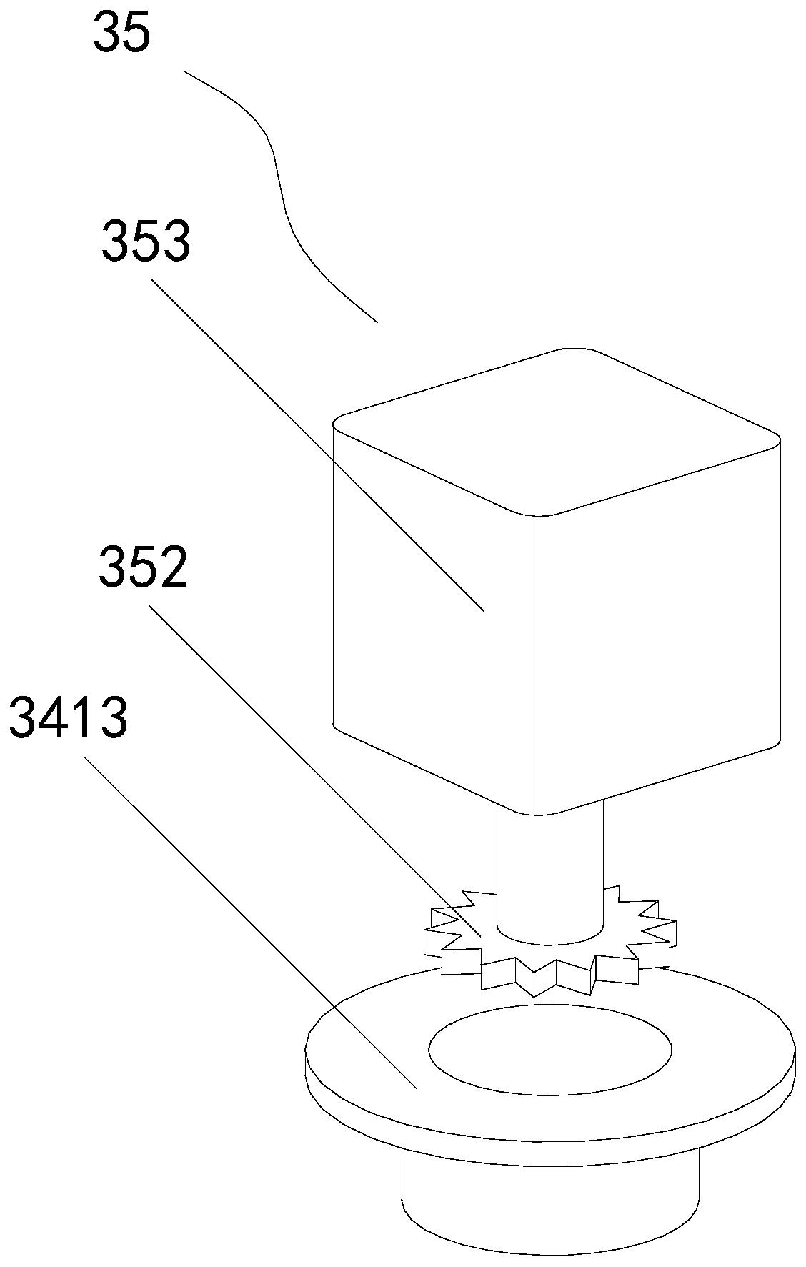
[0039] see Figure 1 to Figure 6, the present invention provides a traction structure 200, including a seat cushion 1, a first backrest 2 and a waist adjustment assembly 3; In the direction away from the seat cushion 1, the waist adjustment assembly 3 is fixedly connected with the first backrest 2, and is rotatably connected with the seat cushion 1, and drives the first backrest 2 and the seat cushion 1 to rotate; The waist adjusting assembly 3 includes a fixed base 31, a rotating support rod 32, a waist fixing member 33, a lateral traction member 34 and a driving member 35, the fixed base 31 is fixedly connected with the seat cushion 1, and is located close to the seat cushion 1. On one side of the first backrest 2 , the rotating support rod 32 is fixedly connected with the first backrest 2 and rotatably connected with the fixed base 31 , and is located near the seat cushion 1 on the first backrest 2 One side of the waist fixing member 33 is fixedly connected with the first ...


PUM


Abstract

The invention discloses a hauling structure and a hauling frame device thereof. A medical worker controls a controller to drive a driving component to put down a first backrest and a second backrest to be in parallel with a cushion, a patient sits on the cushion and puts the back on the first backrest and the second backrest, the controller is controlled to drive the driving component to drive a rotating supporting rod to rotate to drive the first backrest and the second backrest to simultaneously axially, and then the waist of the patient is hauled; and meanwhile, the controller is controlledto drive a rotating stepping motor to drive a rotating inner shell and a fixed shell to rotate so as to drive the second backrest and the first backrest to rotate, shoulders of the patient are pushedto rotate by a horizontally stretched hauling supporting plate, the shoulders and waste of the patient are rotated, and the upper half part of the patient is obliquely hauled, so that a better hauling treatment effect is achieved.

Description

technical field [0001] The invention relates to the field of medical instruments, in particular to a traction structure and a traction frame device thereof. Background technique [0002] At present, orthopedic patients have a variety of diseases and complex conditions, and may have different degrees of temporary or permanent dysfunction, causing different degrees of psychological and physical damage to the patients. In addition, the treatment time in bed is long, requiring patient care by medical staff. Traction care is the use of appropriate continuous traction and anti-traction to achieve the restoration and maintenance of fractures or dislocations. Traction is often required for patients to correct postoperative bones or treat other aspects, and sometimes even requires continuous treatment. Perform skeletal traction. [0003] The existing lumbar traction is to draw the patient with the crotch as the axis, and draw the waist towards the legs, or draw the patient towards t...

Claims


Application Information

Patent Timeline
Patent Type & Authority Applications(China)
IPC IPC(8): A61F5/042
CPCA61F5/042
Inventor 王雲蛟卞旭廷唐康来朱敏张臣科马林
Owner THE FIRST AFFILIATED HOSPITAL OF ARMY MEDICAL UNIV
Why Eureka
Try Eureka