
Rotary air blowing roller for assisting film rolling

A film and air roller technology, applied in the direction of winding strip, thin material handling, transportation and packaging, etc., can solve the problems of long distance of air blowing nozzle, long winding time and low air blowing pressure, and avoid manual operation. , The effect of stable rolling and space saving

Inactive Publication Date: 2020-06-05
LAIWU VOCATIONAL & TECHNICAL COLLEGE
View PDF0 Cites 0 Cited by
  • Summary
  • Abstract
  • Description
  • Claims
  • Application Information

AI Technical Summary

Problems solved by technology

[0004] This application is to solve the problem that the existing film has a high degree of danger when it is rolled up and is not suitable for high-speed automatic winding; at the same time, the position of the existing air blowing nozzle is set at a relatively large distance from the film, which is often suitable for relatively thin films, so The scope of application is narrow, and the blowing nozzle is far away, resulting in long winding time and low blowing pressure, which to a large extent prevents the film from entering the core for winding; therefore, a rotating blowing roller is designed to assist film winding , which is specifically:

Method used


Image

  • Rotary air blowing roller for assisting film rolling
  • Rotary air blowing roller for assisting film rolling
  • Rotary air blowing roller for assisting film rolling

Examples


Embodiment Construction

[0024] In order to clearly illustrate the technical features of this solution, the present invention will be described in detail below through specific implementation methods and in conjunction with the accompanying drawings.

[0025] In addition, in the description of the present invention, it should be understood that the terms "center", "upper", "lower", "front", "rear", "left", "right", "vertical", "horizontal" ", "Top", "Bottom", "Inner", "Outer", "Axial", "Radial", "Circumferential" and other indicated orientations or positional relationships are based on the orientations or positional relationships shown in the drawings , is only for the convenience of describing the present invention and simplifying the description, but does not indicate or imply that the referred device or element must have a specific orientation, be constructed and operated in a specific orientation, and thus should not be construed as limiting the present invention.

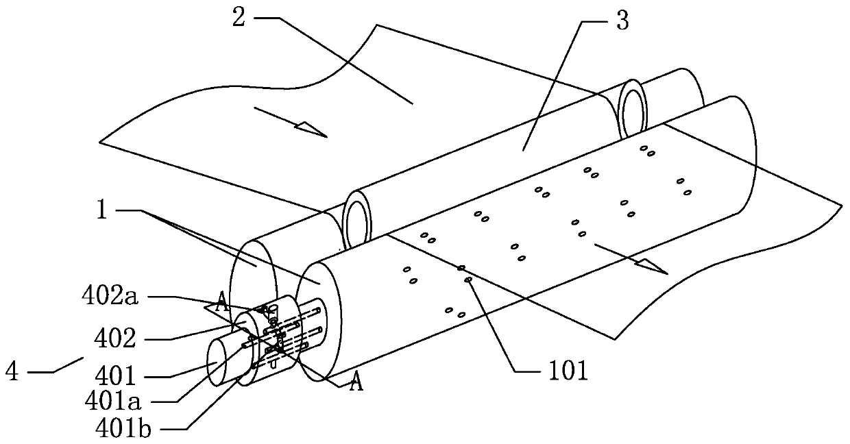
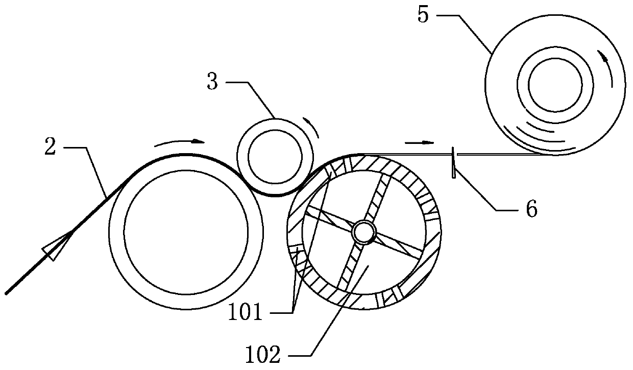
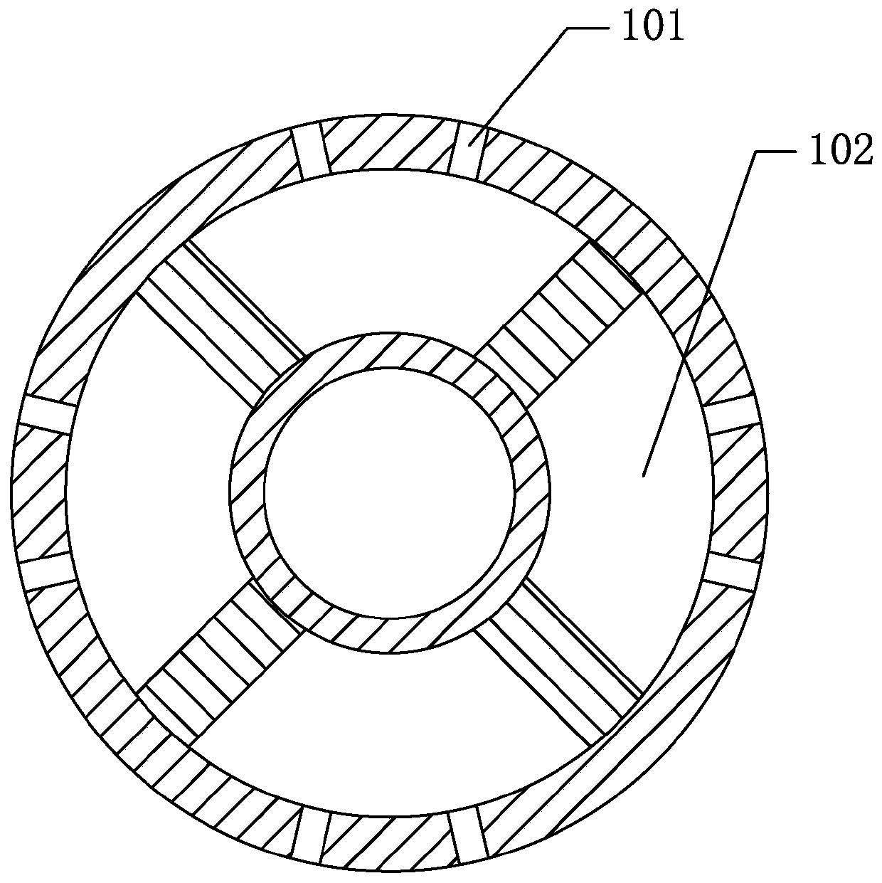
[0026] Such as Figure 1-4 As ...


PUM


Abstract

The invention relates to a rotary air blowing roller for assisting film rolling, and relates to a film winding part. The rotary air blowing roller comprises two carrier rollers, a rolling core and a rotating joint wherein the two carrier rollers and the rolling core are arranged in an isosceles triangle shape, the central axis of the rolling core is located on the perpendicular bisector of the connecting line of the central axes of the two carrier rollers, at least two air cavities are formed in one of the carrier rollers, the air cavities are independent from one another, air blowing holes are formed in positions, corresponding to the air cavities, of the circumferential surface of the one of the carrier rollers correspondingly, the air blowing holes are formed in the radial direction ofthe one of the carrier rollers, the rotating joint is connected with the end face of the one of the carrier rollers, an air inlet is formed in the rotating joint, and the air inlet always communicateswith the air cavity close to the rolling core, so that air enters the air cavity close to the rolling core through the rotating joint, and a film is blown to the rolling core through the air blowingholes. In this way, the space can be saved, blowing force is large, the broken thin film can be only attached to the surface of the rolling core, rolling is stable, and the roller is suitable for high-speed automatic thin film rolling.

Description

technical field [0001] The invention relates to a film winding part, in particular to a rotating blowing roller for assisting film winding. Background technique [0002] As the demand for automation equipment in the plastic film industry becomes more and more urgent, being able to complete automatic winding of all film types in a stable and reliable manner will greatly promote the development of the industry. This is also a technical problem faced by automatic winding at present. . Existing plastic film often adopts two ways in order to make the film after cutting automatically roll up on the winding core after cutting. First, the tape method, which mainly relies on manual double-sided tape to be wrapped on the core in advance. After the film is cut, the film is attached by tape to complete the winding. The above winding and winding method cannot be used for automatic core supply, because the tapes wrapped in advance will stick together because the cores are close to each ...

Claims


Application Information

Patent Timeline
Patent Type & Authority Applications(China)
IPC IPC(8): B65H19/28B65H19/30B65H19/26
CPCB65H19/26B65H19/28B65H19/30B65H2701/175
Inventor 李传红张正洲
Owner LAIWU VOCATIONAL & TECHNICAL COLLEGE
Learn More