Electrophoretic painting device for car door

A technology for electrophoretic painting and car doors, which is applied in the directions of electrolytic paint, electrophoretic plating, and coating, and can solve the problems of car door prolapse and low versatility of electrophoretic paint tooling.

Active Publication Date: 2021-11-19
DONGFENG LIUZHOU MOTOR
View PDF0 Cites 1 Cited by
  • Summary
  • Abstract
  • Description
  • Claims
  • Application Information

AI Technical Summary

Problems solved by technology

[0003] The technical problem to be solved by the present invention is to provide an electrophoretic painting device for car doors to solve the problems that the existing electrophoretic painting tooling for car doors has low versatility and the doors are prone to falling out

Method used


Image

  • Electrophoretic painting device for car door
  • Electrophoretic painting device for car door
  • Electrophoretic painting device for car door

Examples


Embodiment 1

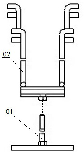
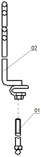
[0022] The car door electrophoretic painting device shown in 7 includes a support rod 1. The support rod 1 in this embodiment has a vertical rod section 1-2 with a limit block 1-3 welded at one end and the other end of the vertical rod section 1-2 is connected. The horizontal bar section 1-1, the vertical bar section 1-2 and the horizontal bar section 1-1 are arranged at right angles, and the angle c between the vertical bar section 1-2 and the horizontal bar section 1-1 in this embodiment is 90° °; the other end of the cross bar section 1-1 is connected with a lower folding bar section 1-4 inclined to the limit block 1-3 side, and the folding bar section 1-4 is connected with an upper folding bar section 1-5; The angle d between the horizontal bar section 1-1 and the lower folding bar section 1-4 of the embodiment is 105°, and the included angle f between the lower folding bar section 1-4 and the upper folding bar section 1-5 is 130° °, the above-mentioned included angle c, i...

Embodiment 2

[0024] The car door electrophoretic painting device shown in 7 includes a support rod 1. The support rod 1 in this embodiment has a vertical rod section 1-2 with a limit block 1-3 welded at one end and the other end of the vertical rod section 1-2 is connected. The horizontal bar section 1-1, the vertical bar section 1-2 and the horizontal bar section 1-1 are arranged at right angles, and the angle c between the vertical bar section 1-2 and the horizontal bar section 1-1 in this embodiment is 90° °; the other end of the cross bar section 1-1 is connected with a lower folding bar section 1-4 inclined to the limit block 1-3 side, and the folding bar section 1-4 is connected with an upper folding bar section 1-5; The angle d between the horizontal bar section 1-1 and the lower folding bar section 1-4 of the embodiment is 115°, and the included angle f between the lower folding bar section 1-4 and the upper folding bar section 1-5 is 140° °, the above-mentioned included angle c, i...


PUM


Abstract

The invention discloses an electrophoretic painting device for car doors, which comprises a support rod. The support rod has a vertical bar section with a limit block at one end and a horizontal bar section connected to the other end of the vertical bar section. The other end of the horizontal bar section is connected with a The lower folding rod section inclined to one side of the limit block, the lower folding rod segment is connected with the upper folding rod segment; the angle between the upper folding rod segment and the lower folding rod segment and the angle between the lower folding rod segment and the cross bar segment The included angles are all obtuse angles; there is a drum mounted on the vertical rod section, and the drum has a drum body, a limit rod and a weight limit rod arranged on the upper part of the drum body; the axis line of the drum body The angle between the axis line of the weight limit rod and the axis line of the limit rod is obtuse, and the axis line of the weight limit rod and the axis line of the limit rod are set at 180°. The quality of the hammer limit rod is greater than the quality of the limit rod. Compared with the prior art, the present invention can solve the problems that the electrophoretic painting tooling of the existing car door has low versatility and the car door is easy to come out.

Description

technical field [0001] The invention relates to the technical field of car door electrophoretic paint manufacturing, in particular to a car door electrophoretic tooling commonly used in SUV models and MPV models. Background technique [0002] Before the sedan is put into production, the front door electrophoresis tooling of the existing SUV and MPV models is common, and the purpose of these electrophoresis tooling is to clamp the open door limit and prevent it from coming out; figure 1 and figure 2 The shown front door electrophoresis tooling includes a hook plate 02 equipped with a screw rod 01, struts are provided at both ends of the hook plate 02, and a plurality of symmetrically arranged openings facing outwards are respectively arranged on the two struts. Card slot; when in use, clamp the hook plate 02 of the front door electrophoresis tooling on the welding stop 05 of the horizontal glass groove of the door near the vertical glass groove of the door 04, then open the...

Claims


Application Information

Patent Timeline
Patent Type & Authority Patents(China)
IPC IPC(8): C25D13/12C25D13/22
CPCC25D13/12C25D13/22
Inventor 彭进乐
Owner DONGFENG LIUZHOU MOTOR
Why Eureka
Try Eureka