Intelligent luminous wood floor

A wooden floor, intelligent technology, applied in the field of floor decoration, can solve the problems of reducing the service life of the floor, high calorific value and energy consumption, destroying lamp beads, etc., to achieve the effect of improving the service life, improving the design space, and increasing the decorative performance.

Pending Publication Date: 2020-06-05
DAYA JIANGSU FLOOR +1
View PDF1 Cites 4 Cited by
  • Summary
  • Abstract
  • Description
  • Claims
  • Application Information

AI Technical Summary

Problems solved by technology

The deficiencies of this prior art are: 1. The entire surface of the prior art is made of wear-resistant light-transmitting boards, not solid wood flooring. Solid wood flooring is a biomass material, which has the characteristics of swelling when wet and shrinking when dry. Difficult to combine with electronic components, the present invention aims to overcome and solve this problem. Under the premise of not destroying the structure of the solid wood floor, the unique wood texture of the floor surface is kept beautiful, and no trace of any lamp can be seen when it is not emitting light; 2. The prior art is square Flooring materials, pavement and line connection are simple, and long-strip wooden floor misalignment leads to higher technical requirements for line connection; 3. Pressure sensors are placed in more than half of the existing technology, which is costly; 4. The integrated design of the existing technology The gravitational force in the process of people walking is bound to generate greater pressure on the light-transmitting plate on the groove, which greatly reduces the service life of the floor and may damage the lamp beads; 5. The existing technology uses LED Lamp beads, the bigger and denser the lamp beads, the higher the heat generation and energy consumption

Method used


Image

  • Intelligent luminous wood floor
  • Intelligent luminous wood floor
  • Intelligent luminous wood floor

Examples


Embodiment 1

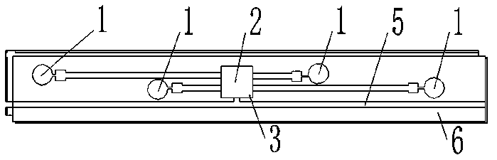
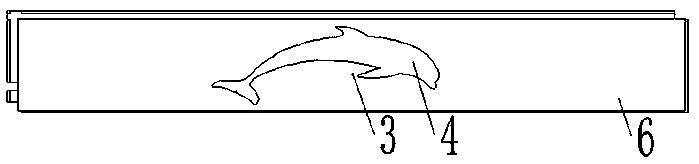
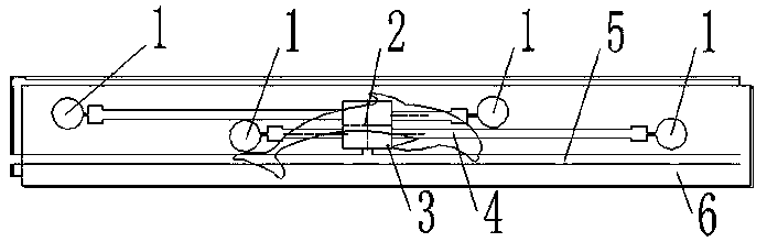
[0025] An intelligent luminous wooden floor, comprising a wooden floor body 6, an upper groove, and a lower groove. The upper groove is inlaid with a thin and narrow luminous pattern element 5, and the luminous pattern element 5 is waterproofed and sealed with epoxy resin and then coated. Covered with paint, the lower groove is inlaid with a vibration sensor and a control circuit board, the upper groove and the lower groove are connected through a drill hole 3, and the control circuit board in the lower groove is connected to the external sensor for inducing sunlight intensity. The illuminance meter is electrically connected to a 5~24V power supply. The lower groove is composed of a quadrilateral groove 2 in the middle and a circular groove 1 around it. A circuit board is arranged in the quadrilateral groove 2, and a vibration sensor is installed in the circular groove 1. For the sensor, a wire groove 4 is arranged between the circular groove 1 and the quadrangular groove 2 and...

Embodiment 2

[0028] An intelligent luminous wooden floor, comprising a wooden floor body 6, an upper groove, and a lower groove. The upper groove is inlaid with a thin and narrow luminous pattern element 5, and the luminous pattern element 5 is waterproofed and sealed with epoxy resin and then coated. Covered with paint, the lower groove is inlaid with a pressure sensor and a control circuit board, the upper groove and the lower groove are connected through a drill hole 3, and the control circuit board in the lower groove is connected to the external sensor for sensing the intensity of sunlight. The illuminance meter is electrically connected to a 5~24V power supply. The lower groove is composed of a quadrilateral groove 2 in the middle and a circular groove 1 around it. A circuit board is arranged in the quadrilateral groove 2, and a pressure gauge is respectively set in the circular groove 1. For the sensor, a wire groove 4 is arranged between the circular groove 1 and the quadrangular gr...

Embodiment 3

[0031] An intelligent luminous wooden floor, comprising a wooden floor body 6, an upper groove, and a lower groove. The upper groove is inlaid with a thin and narrow luminous pattern element 5, and the luminous pattern element 5 is waterproofed and sealed with epoxy resin and then coated. Covered with paint, the lower groove is inlaid with a microwave sensor and a control circuit board, the upper groove and the lower groove are communicated through a drill hole 3, and the control circuit board in the lower groove is connected to the external sensor for sensing the intensity of sunlight. The illuminance meter is electrically connected to a 5~24V power supply. The lower groove is composed of a quadrilateral groove 2 in the middle and a circular groove 1 around it. A circuit board is arranged in the quadrilateral groove 2, and a microwave oven is respectively arranged in the circular groove 1. For the sensor, a wire groove 4 is arranged between the circular groove 1 and the quadra...


PUM


Abstract

The invention belongs to the technical field of floor decoration, and relates to an in intelligent luminous wood floor. The intelligent luminous wood floor comprises a wood floor body, an upper grooveand a lower groove. A thin and narrow luminous pattern element is embedded in the upper groove, a sensor and a control circuit board are embedded in the lower groove, the upper groove and the lower groove communicate through a drill hole, the control circuit board in the lower groove is electrically connected with an illuminometer which is externally mounted and used for inducing sunlight intensity and a 5-24V power source, the lower groove is composed of a square groove in the middle and round grooves in the periphery, a circuit board is mounted in the square groove, sensors are mounted in the round grooves, and wire grooves are mounted between the round grooves and the square groove and communicate with an outer power line. A light-emitting unit is separated from a control part, the service life of the floor can be prolonged, the design space of the luminous pattern element is increased, the floor decoration property is improved, customer interest is increased, and the better marketprospect is achieved.

Description

technical field [0001] The invention belongs to the technical field of floor decoration, in particular to an intelligent luminous wooden floor. Background technique [0002] At present, most solid wood composite floors only have basic functions, such as floor comfort, wear resistance, scratch resistance, and aesthetic performance as a flooring material. Few floors with intelligent features appear. However, with the development of science and technology, users require more multi-functional products in various aspects. When people get up at night, they often need to turn on and turn off the lights. The light source that suddenly lights up in the dark will cause greater irritation to the human eyes; although there are many night lights on the market, although the light of the night lights is weak, However, many people who are sensitive to light are still not suitable for night lights, which can easily cause sleep disorders. The smart luminous floor at night meets the needs of...

Claims


Application Information

Patent Timeline
Patent Type & Authority Applications(China)
IPC IPC(8): E04F15/02E04F15/04E04F15/18F21V33/00
CPCE04F15/02E04F15/04E04F15/18E04F2290/026E04F2290/04F21V33/0004
Inventor 张岩王素鹏宋晖东
Owner DAYA JIANGSU FLOOR
Why Eureka
Try Eureka