Method and device for determining rotor phase of compressor, compressor

A rotor phase and determination method technology, applied in the field of compressor control, can solve problems such as low reliability, abnormal compressor vibration, inaccurate compressor torque compensation, etc.

Active Publication Date: 2020-12-18
GREE ELECTRIC APPLIANCES INC
View PDF9 Cites 0 Cited by
  • Summary
  • Abstract
  • Description
  • Claims
  • Application Information

AI Technical Summary

Problems solved by technology

[0005] Embodiments of the present invention provide a method and device for determining the rotor phase of a compressor, and a compressor, at least to solve the problem of low reliability in obtaining the phase of the compressor rotor in the related art, so that torque compensation is performed on the compressor Inaccurate, easy to cause technical problems of abnormal compressor vibration

Method used


Image

  • Method and device for determining rotor phase of compressor, compressor
  • Method and device for determining rotor phase of compressor, compressor
  • Method and device for determining rotor phase of compressor, compressor

Examples


Embodiment 1

[0035] According to an embodiment of the present invention, a method embodiment of a method for determining the rotor phase of a compressor is provided. It should be noted that the steps shown in the flow charts of the accompanying drawings can be implemented in a computer system such as a set of computer-executable instructions and, although a logical order is shown in the flowcharts, in some cases the steps shown or described may be performed in an order different from that shown or described herein.

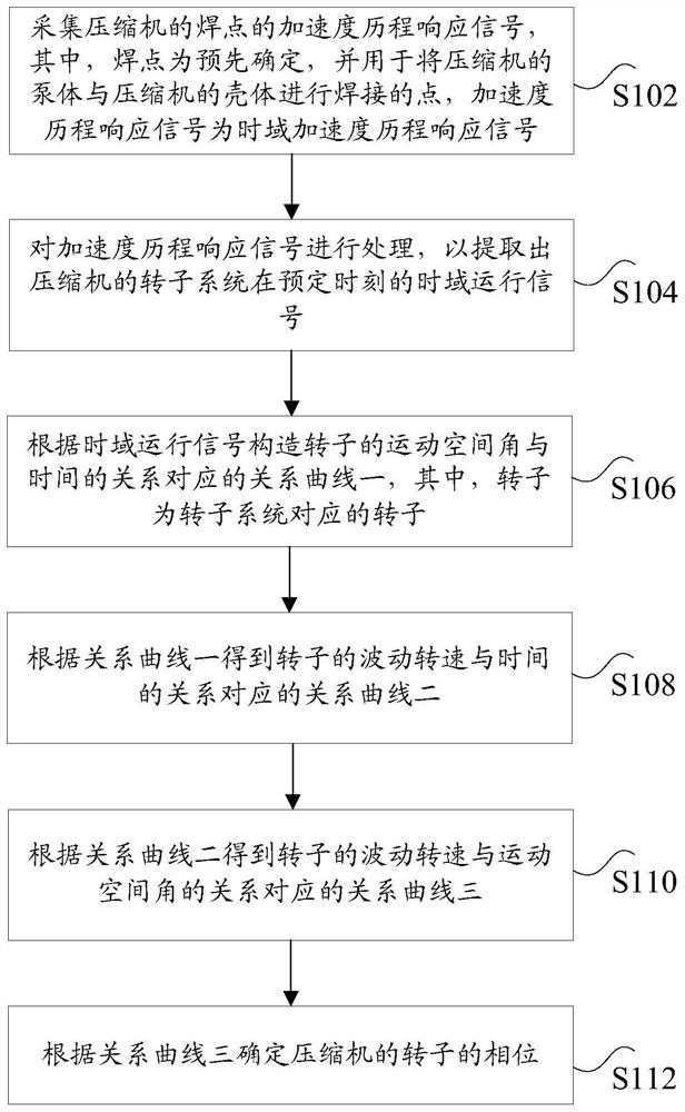
[0036] figure 1 is a flowchart of a method for determining the rotor phase of a compressor according to an embodiment of the present invention, such as figure 1 As shown, the method for determining the rotor phase of the compressor includes the following steps:

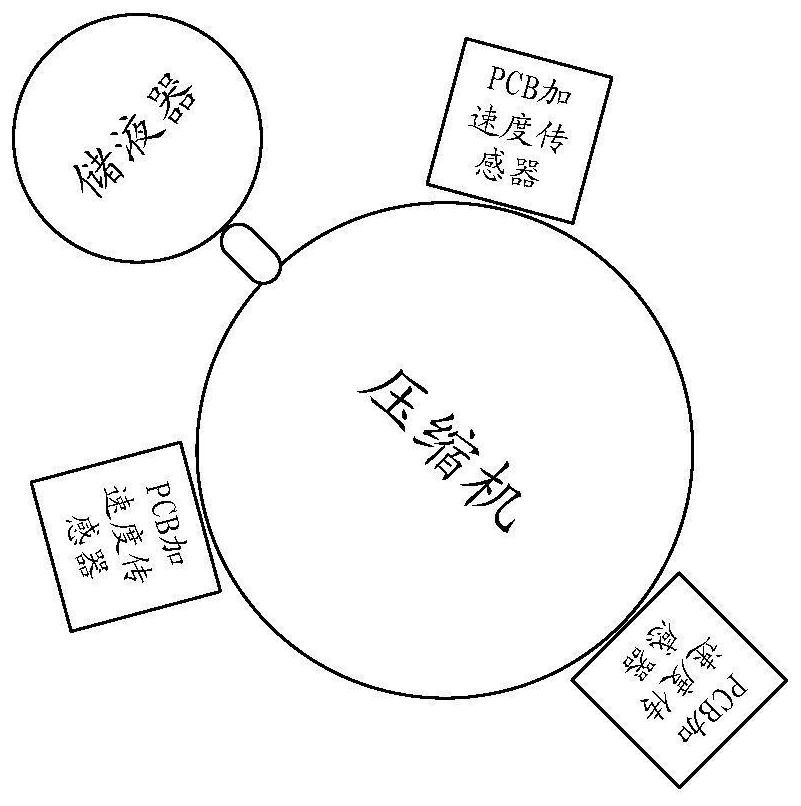
[0037] Step S102, collect the acceleration history response signal of the welding point of the compressor, wherein the welding point is a predetermined point for welding the pump body of the compressor and the shell ...

Embodiment 2

[0065] According to another aspect of the embodiments of the present invention, a device for determining the rotor phase of a compressor is also provided, Figure 5 is a schematic diagram of a device for determining the rotor phase of a compressor according to an embodiment of the present invention, such as Figure 5 As shown, the device for determining the rotor phase of the compressor includes: an acquisition unit 51 , a processing unit 52 , a first construction unit 53 , a second construction unit 54 , a third construction unit 55 and a determination unit 56 . The device for determining the rotor phase of the compressor will be described in detail below.

[0066] The acquisition unit 51 is used to collect the acceleration history response signal of the welding point of the compressor, wherein the welding point is a predetermined point for welding the pump body of the compressor and the shell of the compressor, and the acceleration history response signal is Time domain acc...

Embodiment 3

[0082] According to another aspect of the embodiments of the present invention, a compressor is also provided, using any one of the methods for determining the rotor phase of the compressor described above.


PUM


Abstract

The invention discloses a determining method and device for a rotor phase of a compressor and the compressor. The method comprises the following steps: acquiring an accelerated speed course response signal of a welding spot of the compressor; processing the accelerated speed course response signal to extract a time domain operation signal, at a predetermined moment, of a rotor system of the compressor; constructing a relation curve I which corresponds to a relationship between a motion space angle of a rotor and time according to the time domain operation signal, wherein the rotor is a rotor corresponding to the rotor system; obtaining a relation curve II which corresponds to a relationship between fluctuation rotation speed of the rotor and time according to the relation curve I; obtaining a relation curve II which corresponds to a relationship between the fluctuation rotation speed of the rotor and the motion space angle of the rotor according to the relation curve II; and determining the phase of the rotor of the compressor according to the relation curve III. The determining method solves the technical problem that the compressor is easily caused to vibrate abnormally as a result of inaccurate torque compensation on the compressor if a way of obtaining the phase of the rotor of the compressor in the prior art is lower in reliability.

Description

technical field [0001] The invention relates to the technical field of compressor control, in particular, to a method and device for determining a rotor phase of a compressor, and a compressor. Background technique [0002] The compressor rotor phase signal is of great significance for compressor vibration control, especially for torque compensation. Transitional compensation or untimely compensation will lead to abnormal vibration of the compressor; at present, the extraction of compressor rotor phase is mainly through the use of compressor electrical signal identification The rotor phase method, in which the compressor electrical signal mainly refers to identifying the rotor position information by collecting the back electromotive force in the motor winding, the process of signal acquisition input, signal calculation, signal output, etc. will cause a certain gap between the calculated rotor phase and the actual rotor phase. The deviation will eventually cause the torque c...

Claims


Application Information

Patent Timeline
Patent Type & Authority Patents(China)
IPC IPC(8): F04C28/28
CPCF04C28/28
Inventor 杨阳梁凯何维令
Owner GREE ELECTRIC APPLIANCES INC
Why Eureka
Try Eureka