
Mounting hanging bracket for multi-station conference projection equipment

A projection equipment and multi-station technology, which is applied in the direction of mechanical equipment, projection devices, machines/stands, etc., can solve problems such as low versatility, single application, and potential safety hazards, so as to avoid potential safety hazards, apply widely, and reduce height Effect

Inactive Publication Date: 2020-06-05
乔正全
View PDF1 Cites 4 Cited by
  • Summary
  • Abstract
  • Description
  • Claims
  • Application Information

AI Technical Summary

Problems solved by technology

[0005] The purpose of the present invention is to provide a mounting hanger for multi-station conference projection equipment, to solve the low versatility proposed in the above background technology, most of them are customized for a certain type of projector, and can only be fixedly installed One type of projector, and the lens dust cover is mostly fixed, which cannot be used to cover the lenses in different positions on different models of projectors. , the climbing operation is cumbersome and inconvenient, and has certain safety hazards

Method used


Image

  • Mounting hanging bracket for multi-station conference projection equipment
  • Mounting hanging bracket for multi-station conference projection equipment
  • Mounting hanging bracket for multi-station conference projection equipment

Examples


Embodiment Construction

[0030] The following will clearly and completely describe the technical solutions in the embodiments of the present invention with reference to the accompanying drawings in the embodiments of the present invention. Obviously, the described embodiments are only some, not all, embodiments of the present invention.

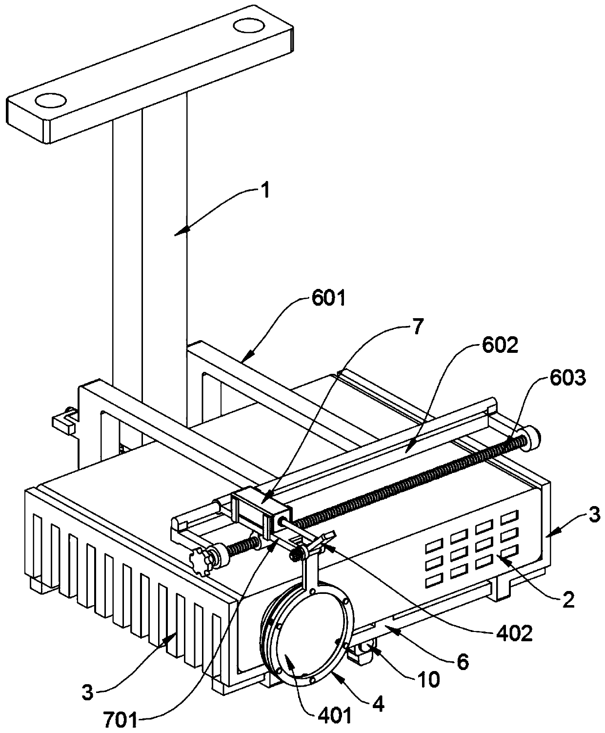
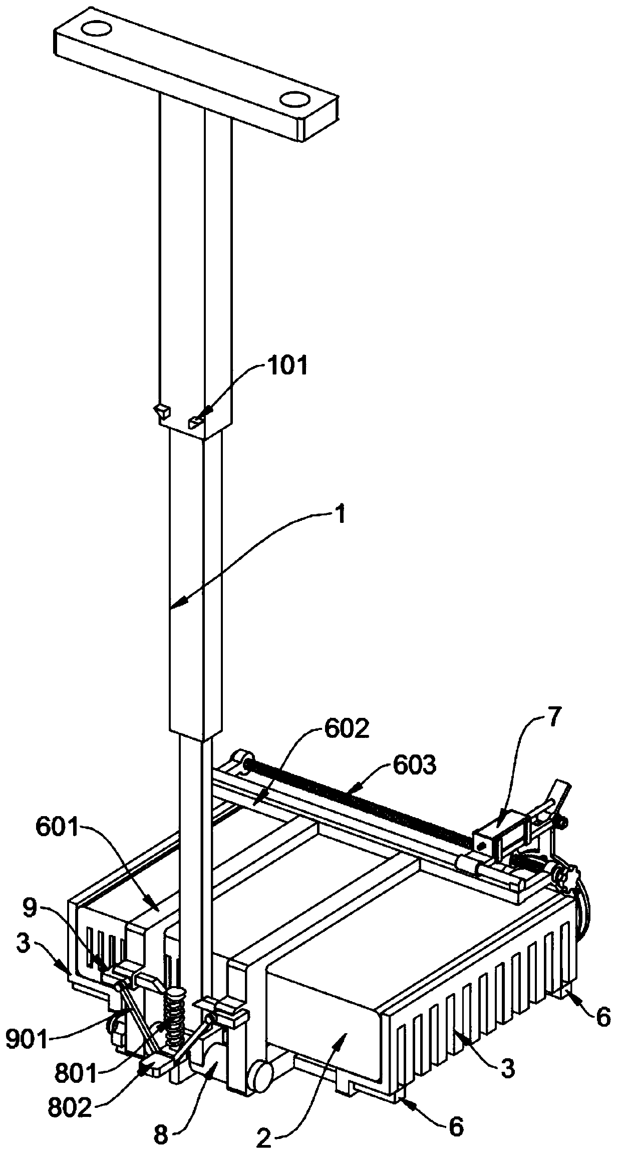
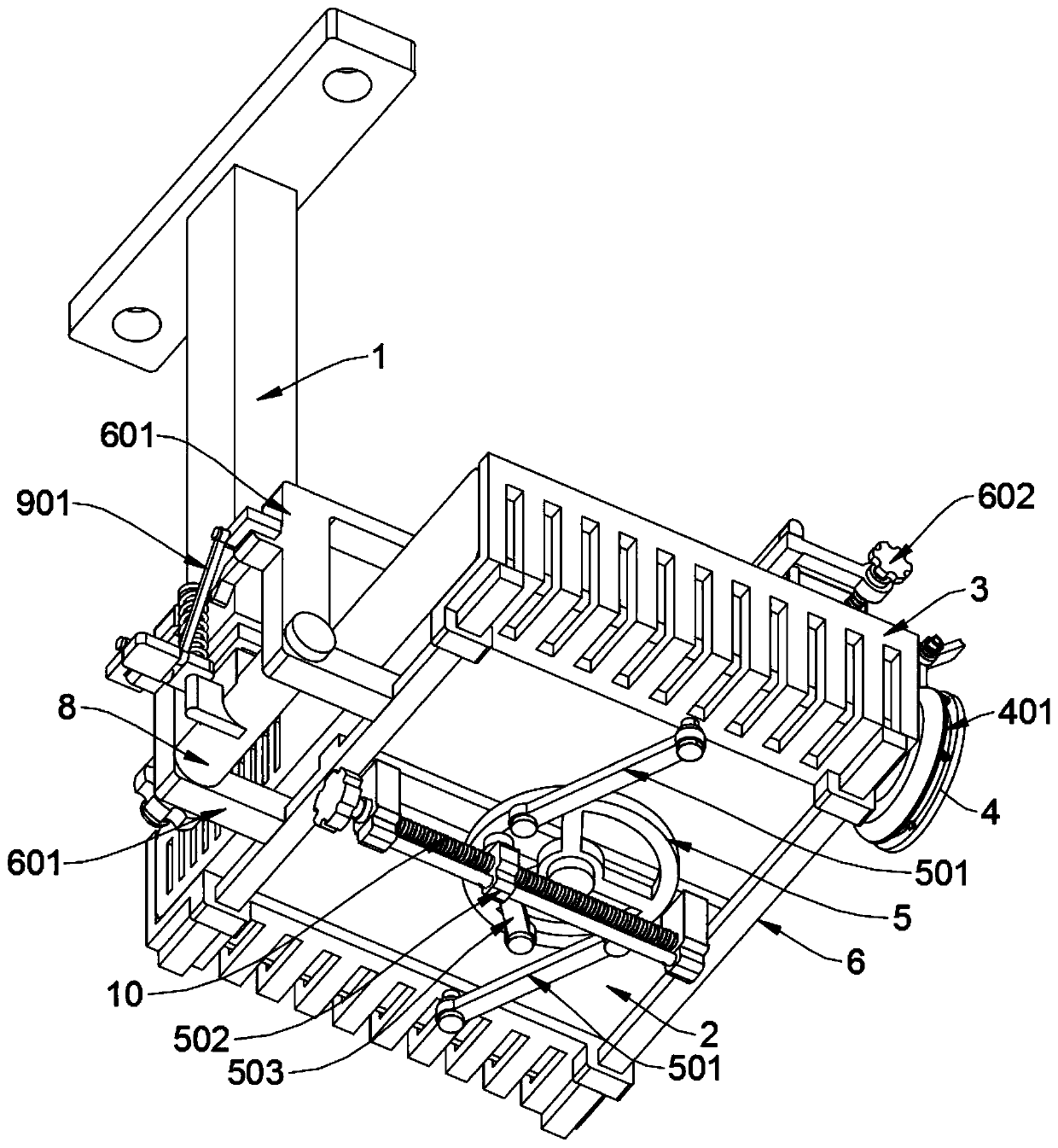
[0031] see Figure 1 to Figure 10, an embodiment provided by the present invention: an installation hanger for multi-station conference projection equipment, including a telescopic hanger 1, a clip bar 3, a support bracket 6, an electromagnetic push rod 7 and a top insertion rod 9, The telescopic boom 1 includes a positioning wedge 101. The telescopic boom 1 is a three-stage piston telescopic setting. Two positioning wedges 101 protrude symmetrically from the bottom side of the back of the outermost square rod sleeve, and the telescopic boom 1 The bottom of the innermost piston square rod is welded and fixed with a positioning bushing 8; the clip bar 3 is L-shaped an...


PUM


Abstract

The invention discloses a mounting hanging bracket for multi-station conference projection equipment, relates to the technical field of projection fixing brackets, and solves the problems that most oflens dust cover plates of existing mounting hanging brackets are fixedly arranged and cannot be suitable for sealing and covering lenses in different positions of different models of projectors and the application is relatively single. The mounting hanging bracket for the multi-station conference projection equipment comprises a telescopic hanger rod, a clamping fence, a supporting bracket, an electromagnetic push rod and ejection inserting rods, wherein the telescopic hanger rod comprises positioning wedge blocks and is a three-section type piston which is telescopically arranged, the two positioning wedge blocks symmetrically bulge out of the bottom side of the back of a square rod sleeve on the outermost layer of the telescopic hanger rod, and a positioning shaft sleeve is welded and fixed at the bottom of a piston square rod on the innermost side of the telescopic hanger rod. By means of ejection sliding fit of oblique planes of the two ejection inserting rods and the two positioning wedge blocks, the supporting bracket and the square rod sleeve on the outer layer of the telescopic hanger rod can be automatically inserted and positioned together, and the telescopic hanger rodis enabled to keep in a shrinking state.

Description

technical field [0001] The invention relates to the technical field of projection fixing frames, in particular to a mounting hanger for multi-station conference projection equipment. Background technique [0002] With the rapid development of modern information processing technology, the requirements for the modernization of conference rooms are getting higher and higher. Therefore, the conference room has gradually evolved from a purely listening, hearing and communication place to a comprehensive multi-functional A large number of electronic equipment such as slide projectors, projectors, video recording and playback equipment, and sound reinforcement equipment have entered the meeting place, making the configuration of the conference system more and more professional and more powerful. [0003] In some large conference rooms or lecture halls, projection equipment is generally fixed on the top of the room. This requires the use of a mounting hanger. For example, the pate...

Claims


Application Information

Patent Timeline
IPC IPC(8): F16M11/04F16M11/16F16M11/28F16M13/02G03B21/54
CPCF16M11/04F16M11/16F16M11/28F16M13/02G03B21/54
Inventor 乔正全
Owner 乔正全
Learn More