Composite gas sensor detection device

A composite gas and detection device technology, applied in the field of sensors, can solve the problems of shortening the test time of the sensor T90, large volume of all-in-one gas chamber, cumbersome assembly, etc., and achieve the effects of shortening the test time, solving the lengthy gas path and various combination methods

Pending Publication Date: 2020-06-05
深圳市万安迪科技有限公司
View PDF0 Cites 7 Cited by
  • Summary
  • Abstract
  • Description
  • Claims
  • Application Information

AI Technical Summary

Problems solved by technology

[0003] Aiming at the deficiencies in the prior art, the technical problem to be solved by the present invention is to provide a sensor detection device for compound gas. The purpose of designing the sensor detection device is to solve the problem of large volume and cumbersome assembly of the traditional multi-in-one gas chamber , at the same time, each sensor can contact the gas in the common gas chamber area for detection, which solves the traditional all-in-one gas chamber lengthy gas path, avoids cross interference during sensor measurement, and greatly shortens the sensor T90 test time

Method used


Image

  • Composite gas sensor detection device
  • Composite gas sensor detection device
  • Composite gas sensor detection device

Examples


Embodiment 1

[0033] Embodiment 1: the concrete structure of the present invention is as follows:

[0034] Please refer to the attached Figure 1-3 , a sensor detection device for composite gas of the present invention, comprising:

[0035] A gas chamber main body 10 is provided with a plurality of independent sensor group installation cavities so that each sensor group is isolated from each other, and the inlet ends of each sensor group installation cavity communicate with a common air cavity so that each sensor 6 can detect gas ;

[0036] The air chamber connector 3 detachably installed on the upper end of the air chamber main body 10, the connection between the air chamber connector 3 and the air chamber main body 10 is provided with a sealing ring to form a sealing structure and in the air chamber A cavity is provided in the chamber connector 3 to accommodate two PCB boards, and a connection portion is provided at the lower end of the air chamber main body 10;

[0037] The sensor gro...

Embodiment 2

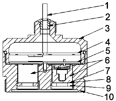
[0050] like figure 1 , 3 as shown, figure 1 It is a structural diagram of a sensor detection device with a diffusion structure in Embodiment 2 of the present invention.

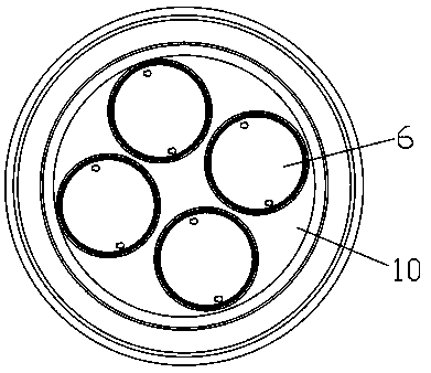
[0051] Overview of Diffusion Structure Composition: Based on image 3 Take the four-in-one air chamber body diffusion type as an example, the sensor 6 is inserted on the pin PCB board, and the pin PCB board is locked on the air chamber main body 10 with a single-headed copper column, and is connected with the signal processing PCB board pin row female, and the signal processing The PCB board is locked on the single-head copper post, the air chamber main body 10 is screwed and fixed with the air chamber joint 3, the sensor 6 is protected by the gasket 7 and the waterproof and dustproof assembly 8, and the gasket 7 and the waterproof and dustproof combination 8 are pressed by the pressure ring 9 The threaded connection with the air chamber main body 10 is fixed.

[0052] The use form and working principle o...

Embodiment 3

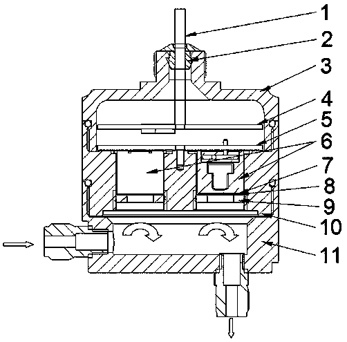
[0054] like Figure 2-3 as shown, figure 2 It is a structural diagram of a flow-through sensor detection device in Embodiment 3 of the present invention.

[0055] Overview of the composition of the flow-through structure: Taking the flow-through type of the main body of the four-in-one air chamber in Figure as an example, a flow-through joint 11 is added on the basis of the diffused structure;

[0056] The use form and working principle of the flow-through structure: the air chamber main body 10 is fixed by the thread on the air chamber joint 3; the air chamber main body 10 is sealed as a whole, and the wiring harness 1 passes through the sealing sleeve 2 and is sealed with the air chamber joint 3 with potting glue, and the air chamber The joint 3 is sealed with the sealing ring of the gas chamber main body 10 , the flow-through joint 11 is sealed with the sealing ring of the gas chamber main body 10 , and the sensor 6 is sealed with a gasket 7 . The gas to be detected flow...


PUM


Abstract

The invention discloses a sensor detection device for composite gas. The sensor detection device comprises a gas chamber main body, a gas chamber connector, a sensor group, a pin PCB and a signal processing PCB. The air chamber body is provided with a plurality of independent sensor set installation cavities so that the sensor sets can be isolated from one another, and the air inlet ends of the sensor set installation cavities are communicated with a public air cavity so that the sensors can detect air. A sealing ring is arranged at the joint of the air chamber connector and the air chamber body to form a sealing structure, a containing cavity is formed in the air chamber connector to contain the two PCBs, and a connecting part is arranged at the lower end of the air chamber body. The problems that a traditional all-in-one air chamber is large in size and complex in assembly are solved. Meanwhile, each sensor can make contact with air in a public air cavity area for detection. The problem that an air path of the traditional all-in-one air chamber is redundant is solved, cross interference during measurement of the sensors is avoided, and the T90 testing time of the sensors is greatly shortened.

Description

technical field [0001] The invention relates to the technical field of sensors, in particular to a sensor detection device for compound gas. Background technique [0002] At present, the combined use of all-in-one sensors for fixed gas detectors on the market is to fix multiple individual sensor gas chambers on one instrument with a fixing device; It is tedious, and the sensor needs to be calibrated separately for each gas chamber; it is often used in diffusion gas detection, and when it is applied to flow-through gas detection, the test time of sensor T90 will be very long, and there will be cross-interference in sensor measurement. Contents of the invention [0003] Aiming at the deficiencies in the prior art, the technical problem to be solved by the present invention is to provide a sensor detection device for compound gas. The purpose of designing the sensor detection device is to solve the problem of large volume and cumbersome assembly of the traditional multi-in-on...

Claims


Application Information

Patent Timeline
Patent Type & Authority Applications(China)
IPC IPC(8): G01N33/00
CPCG01N33/0009G01N33/0011G01N33/0031
Inventor 罗海潮
Owner 深圳市万安迪科技有限公司
Why Eureka
Try Eureka